
Bearizing drilling bit

A technology of reaming drill bit and drill bit, which is applied to drill bits, drilling equipment, earthwork drilling and other directions, can solve the problems such as the deviation of the drilling hole center, the difficulty of retracting the fins, and the inability to retract the reaming fins, so as to improve the reliability. , the effect of avoiding interference

Inactive Publication Date: 2012-06-20
SUNWARD INTELLIGENT EQUIP CO LTD +2
View PDF6 Cites 29 Cited by
  • Summary
  • Abstract
  • Description
  • Claims
  • Application Information

AI Technical Summary

Problems solved by technology

This scheme has the following defects: the wing is greatly affected by the hardness of the soil layer and the rotation speed during drilling, and the diameter of the hole changes.
However, the existing products have the following defects: part of the drilling slag generated during the drilling process is densely accumulated in the irregular cavity between the reaming wing and the drill bit body, such as Image 6 and Figure 7 The cavity 7 of the reaming wing needs to reduce the volume of the cavity 7 when the reaming wing is retracted. If there is drilling slag in the cavity 7, it will hinder the reverse swing of the reaming wing. The dense drilling slag makes it difficult to retract the wing. During the construction, the reaming wing cannot be retracted, the drill bit cannot be taken out from the pile, and the construction failure of the drill bit is excavated by artificial deep pits; the single-wing reaming bit only has one-sided reaming, and the drill bit expands during the drilling process. Affected by the unbalanced resistance of the soil, problems such as center shift and small hole diameter often occur, which cannot meet the construction requirements

Method used


Image

  • Bearizing drilling bit
  • Bearizing drilling bit
  • Bearizing drilling bit

Examples


Embodiment Construction

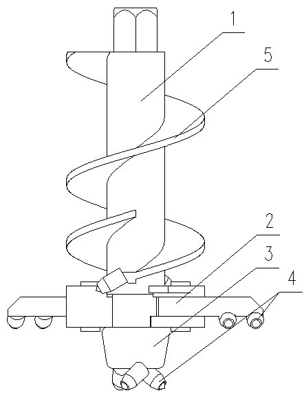
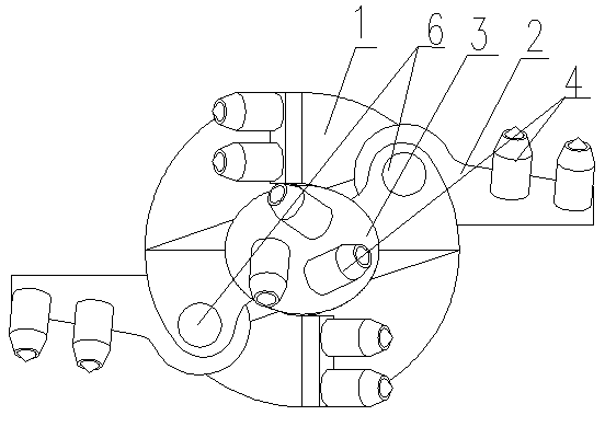
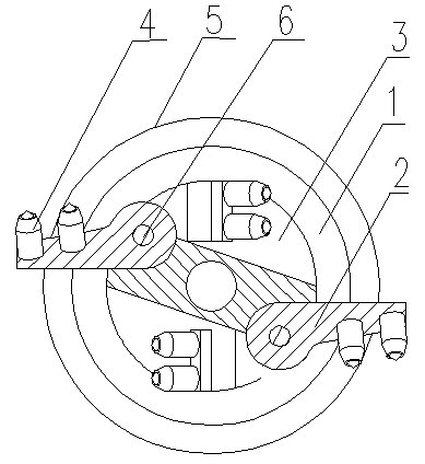
[0023] Such as Figure 1 to Figure 4 For the reaming drill shown, double helical blades 5 are arranged on the side wall of the drill main body 1, and two reaming wings 2 are symmetrically arranged on the drill main body 1 above the drill guide head 3, and the drill main body 1 is symmetrically arranged with The reaming wing 2 has the same number of grooves, one end of the reaming wing 2 is hinged in the groove through the pin shaft 6, and the reaming wing 2 can rotate around the pin shaft 6 to realize retraction and opening, and the reaming wing 2. The connecting end with the drill bit main body 1 is a cylindrical contact surface; the contact surface with the reaming wing 2 in the groove is a cylindrical concave contact surface, and the two have a common center of circle, that is, the axis of the connecting pin 6 of the two. Heart, the two do not form a cavity after cooperation. Drilling teeth 4 are arranged on the drill bit main body 1 , its guiding head 3 , and the reaming ...


PUM


Abstract

The invention discloses a bearizing drilling bit, which is provided with a drilling bit main body and at least one bearizing wing, wherein a spiral blade is arranged on the side wall of the drilling bit main body; grooves, of which the number is the same as that of the bearizing wings, are formed in the drilling bit main body on the upper part of a drilling bit guide head; one end of each bearizing wing is hinged in the corresponding groove through a pin shaft; the bearizing wings can rotate around the pin shafts to open and close; cylindrical concentric matched structures are adopted at the connection ends and on the connection parts of the bearizing wings and the drilling bit main body; and drilling teeth are formed on the guide head, the drilling bit main body and the bearizing wings. The connection parts of the bearizing wings and the drilling bit main body have the cylindrical concentric matched structures, so that a hollow cavity is not formed at a joint between each bearizing wing and the drilling bit main body; therefore, interference of drilling slag on the folding of the bearizing wings is avoided; and the work reliability is improved.

Description

technical field [0001] The invention relates to a drill bit used in pile foundation construction, in particular to a hole reaming drill bit. Background technique [0002] At present, there is a large-diameter pipe-while-drilling drilling rig used in the construction method of mid-drilling pile foundations. The advantage of this drilling rig is that the prefabricated pipe piles follow the drill bit and directly enter the rock and soil layer. The key technology of this construction method is to drill the soil at the bottom of the pipe pile, and the drilled slag is discharged from the pipe pile hole; the diameter of the drilled pile hole must be slightly larger than the outer diameter of the pipe pile, and the drill bit can be easily taken out from the pipe pile after the hole is formed. . [0003] Patent CN2612791Y discloses a reaming drill bit, which includes a drill rod and a drill bit. At least two airfoil drill pieces are mounted on the drill bit. The airfoil drill pieces...

Claims


Application Information

Patent Timeline
IPC IPC(8): E21B10/32E21B10/44
Inventor 朱建新唐孟雄吴新荣单葆岩
Owner SUNWARD INTELLIGENT EQUIP CO LTD
Learn More