
Online detection system for solid-phase internal boundaries and solidification end positions of continuous casting blanks and method

A technology of solidification end and continuous casting billet, applied in the field of steelmaking and continuous casting, can solve the problems of time-consuming and laborious signal-to-noise ratio, inability to realize online detection of the solid phase inner boundary of the continuous casting billet and the position of the solidification end, and reduce heat radiation. , prolong the service life, improve the effect of signal-to-noise ratio

Active Publication Date: 2012-06-20
田志恒
View PDF19 Cites 66 Cited by
  • Summary
  • Abstract
  • Description
  • Claims
  • Application Information

AI Technical Summary

Problems solved by technology

[0016] The present invention aims to provide a system and method for online detection of the solid phase inner boundary and solidification end position of continuous casting slabs to solve the problems of time-consuming and labor-intensive online detection of continuous casting slab solid phase inner boundaries and solidification end positions that cannot be realized by traditional methods. There is a technical problem that the signal-to-noise ratio S / N of the electromagnetic ultrasonic method is too small

Method used


Image

  • Online detection system for solid-phase internal boundaries and solidification end positions of continuous casting blanks and method
  • Online detection system for solid-phase internal boundaries and solidification end positions of continuous casting blanks and method
  • Online detection system for solid-phase internal boundaries and solidification end positions of continuous casting blanks and method

Examples


Embodiment Construction

[0089] The embodiments of the present invention will be described in detail below with reference to the accompanying drawings, but the present invention can be implemented in many different ways defined and covered by the claims.

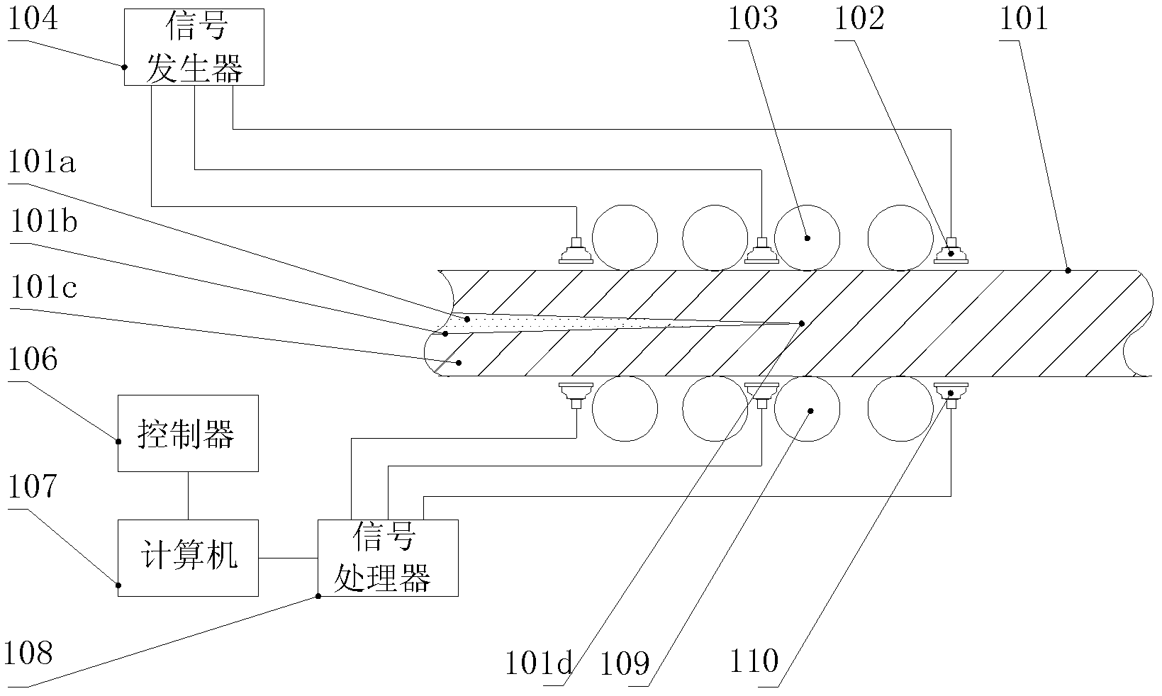
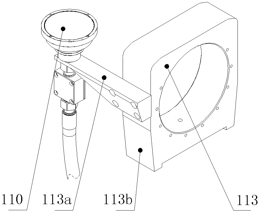
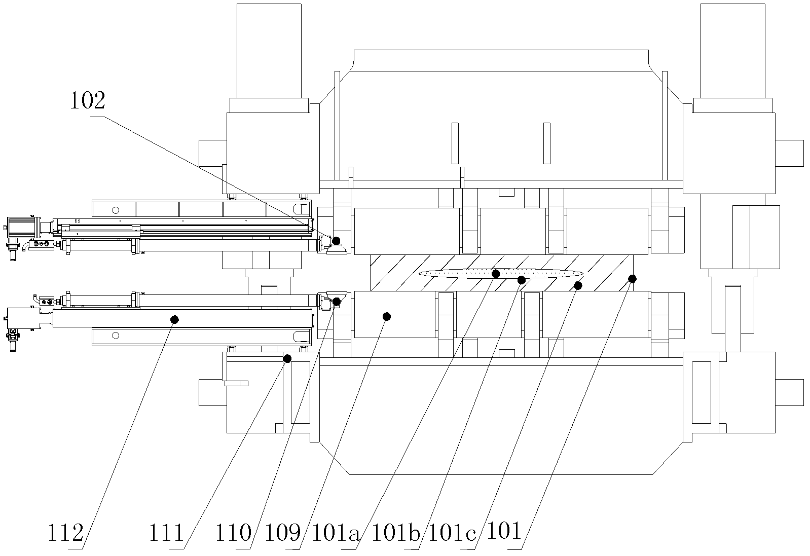
[0090] Figure 1 to Figure 4 Shown is a continuous casting slab solid phase inner boundary and solidification end detection system according to the first embodiment of the present invention. combined reference Figure 1 to Figure 4 , The detection system of the present invention includes: a signal generator 104 , an electromagnetic ultrasonic sensor, a signal processor 108 , a computer 107 and a controller 106 . The signal generator 104 outputs the generated excitation signal to the sensor 102 for emitting electromagnetic ultrasonic waves, and the sensor 110 for receiving electromagnetic ultrasonic waves receives the electromagnetic ultrasonic signals emitted by the sensor 102 for emitting electromagnetic ultrasonic waves and passing through the co...


PUM


Abstract

The invention discloses an online detection system for internal boundaries and solidification end positions of continuous casting blanks and a method. The system comprises a signal generator, electromagnetic ultrasonic sensors, a signal processor, a computer and a controller, wherein the electromagnetic ultrasonic sensors are arranged in dynamically slightly stressed regions in a casting direction of a continuous casting blank and set positions of various fan-shaped sections of local zones of the upstream and the downstream which are adjacent to the regions, and the end area of the end, which faces to the surface of the detected continuous casting blank, of a magnet in each electromagnetic ultrasonic sensor is larger than the end surface of the end, which is far away from the surface of the continuous casting blank, of the magnet in the electromagnetic ultrasonic sensor. In the system, the end area of the end, which faces to the surface of the detected continuous casting blank, of the magnet in each electromagnetic ultrasonic sensor is larger than the end surface of the end, which is far away from the surface of the detected continuous casting blank, of the magnet in the electromagnetic ultrasonic sensor, and accordingly, the signal to noise ratio of electromagnetic ultrasonic waves can be improved. In addition, electromagnetic ultrasonic signals are processed by the computer in screening, shifting, adding and averaging modes, so that the signal to noise ratio of the electromagnetic ultrasonic waves can be greatly increased.

Description

technical field [0001] The invention relates to the field of steelmaking and continuous casting, in particular to a system and method for online detection of the solid phase inner boundary and solidification end position of continuous casting slabs. Background technique [0002] In the continuous casting production process, in order to reduce the center segregation of the continuous casting slab and eliminate defects such as center porosity and cracks, the light reduction technology is usually used, that is, the continuous casting slab at the end of solidification is slightly reduced on the basis of the shrinkage of the roll gap. Prevent the formation of shrinkage voids inside the continuous casting slab, compensate for the shrinkage in the final solidification stage, and improve the internal quality of the slab, such as improving the ductility, welding performance, and crack resistance of steel. [0003] Accurately detecting the inner boundary of the solid phase of the cont...

Claims


Application Information

Patent Timeline
IPC IPC(8): B22D11/16
Inventor 田志恒田立田陆
Owner 田志恒
Learn More