
Ground direct-driving screw pump oil extraction device for switched reluctance motor

A technology of switched reluctance motors and oil extraction devices, which is applied to pumps, mechanical equipment, machines/engines, etc. It can solve the problems that the anti-reverse device is easy to damage itself and the equipment, the speed of the screw pump is difficult, and the system efficiency is low. Reliable and intelligent control reverse electromagnetic brake function, overcome instability of parking brake, and good speed regulation performance

Inactive Publication Date: 2012-06-13
王英浩
View PDF6 Cites 3 Cited by
  • Summary
  • Abstract
  • Description
  • Claims
  • Application Information

AI Technical Summary

Problems solved by technology

[0003] The purpose of the present invention is to provide a switched reluctance motor ground direct-drive screw pump oil production device, to solve the technical problems that the screw pump speed is difficult to adjust, and the reduction box needs frequent maintenance; and to solve the anti-reverse device that is easy to damage itself, equipment and systems The problem of low efficiency

Method used


Image

  • Ground direct-driving screw pump oil extraction device for switched reluctance motor
  • Ground direct-driving screw pump oil extraction device for switched reluctance motor
  • Ground direct-driving screw pump oil extraction device for switched reluctance motor

Examples


Embodiment 1

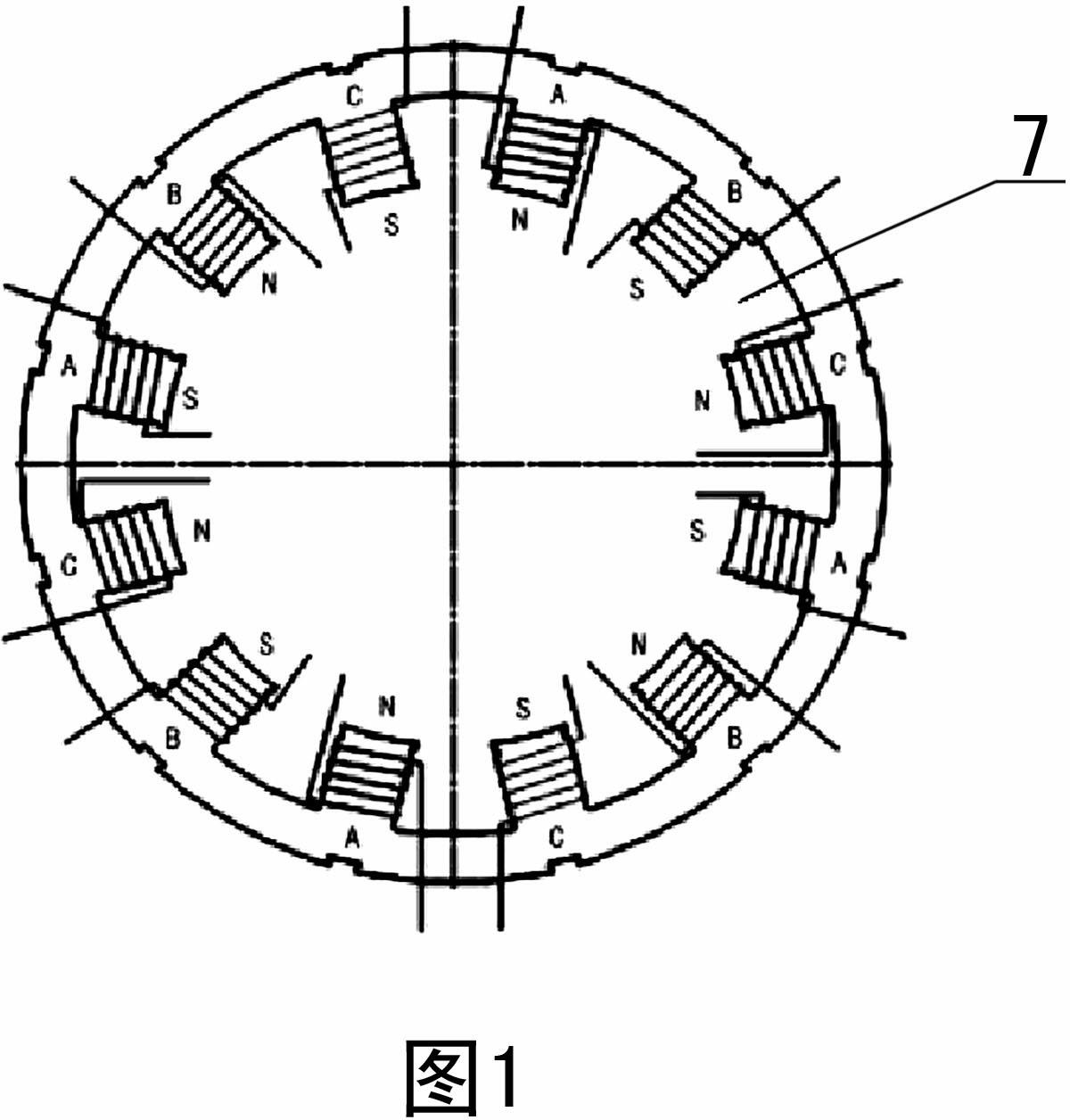
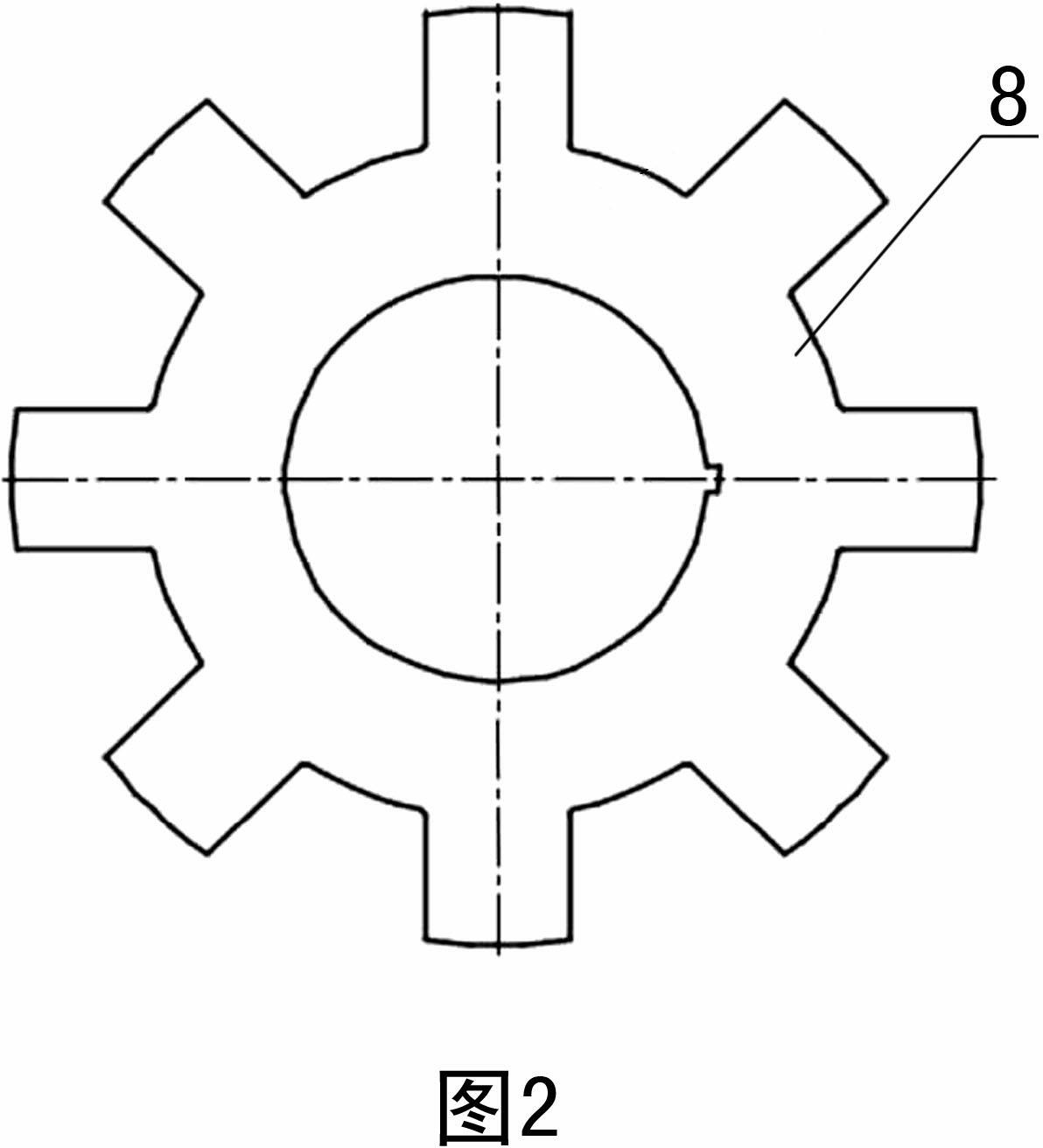
[0021] Embodiment 1: The switched reluctance motor 1 adopts a three-phase 12 / 8 structure, and the stator 7 is provided with three sets of stator teeth arranged radially opposite each other, and each stator tooth is provided with a concentrated winding coil, and the coil interval is divided into three phases , lead out from the cable, and the polarity distribution of each winding current is staggered when it flows in from the head end; the rotor 8 is provided with four groups of eight rotor teeth.

Embodiment 2

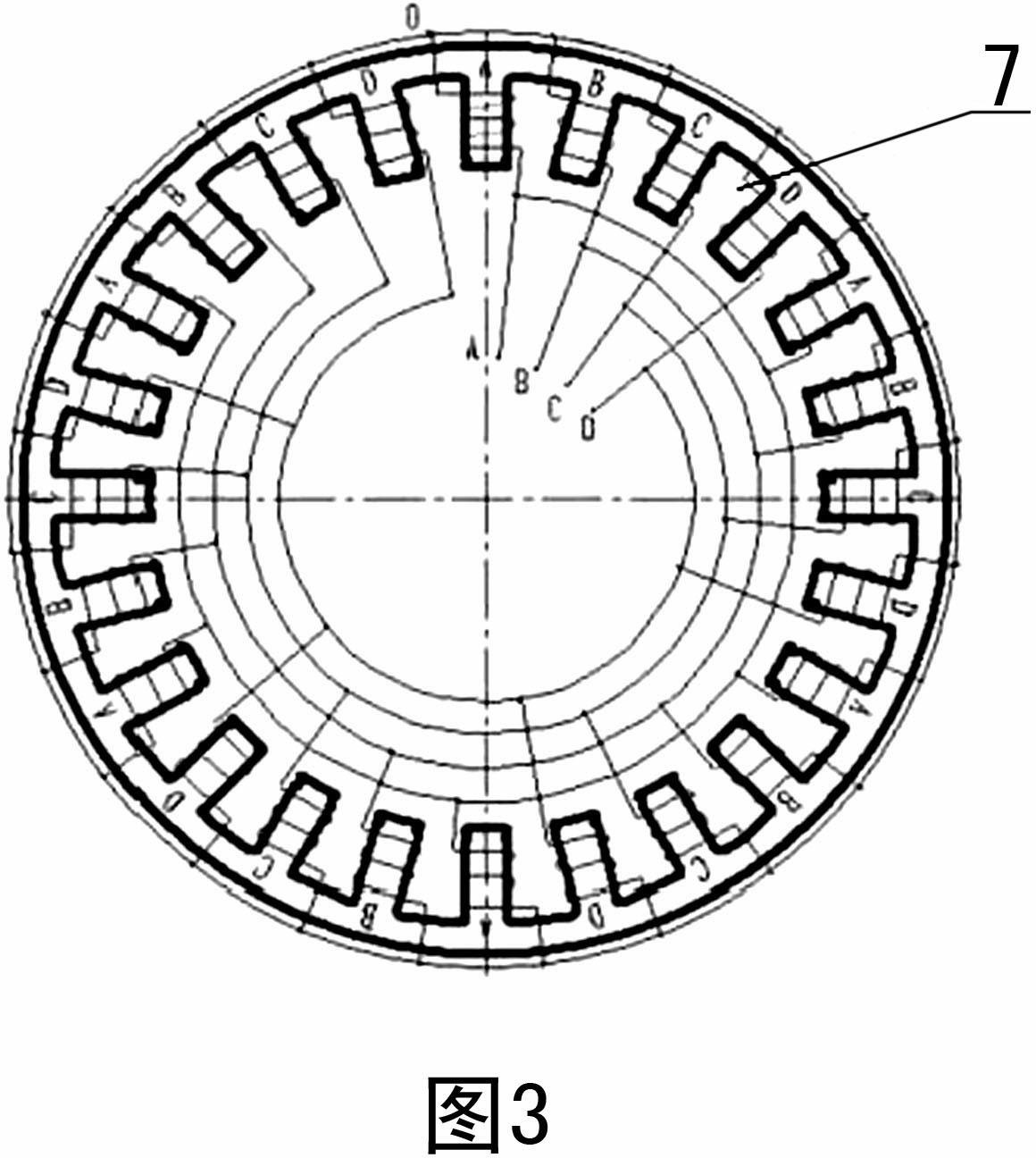
[0022] Embodiment 2: The switched reluctance motor 1 adopts a four-phase 24 / 18 structure, and the stator 7 is provided with four groups of radially opposite stator teeth, and each stator tooth is provided with a concentrated winding coil, and the coil interval is divided into four The phases are led out by cables, and the polarity distribution of each winding is staggered when the current flows in from the head end; the rotor 8 is provided with four groups of eighteen rotor teeth. The switched reluctance motor 1 of the present invention is designed for low-speed and high-torque occasions. The switched reluctance motor adopts two different structures depending on the power used and the size of the motor, which is convenient for users to use.

[0023] See attached Figure 5-6 As shown, the structural block diagram and connection schematic diagram of the switched reluctance motor drive system. This switched reluctance motor surface direct-drive screw pump oil production device i...


PUM


Abstract

The invention comprises a motor on the ground, a control system, a well mouth device, an underground oil pipe, an underground sucker rod and an underground screw pump, wherein the motor comprises a stator, a rotor and a motor-driven shaft; the stator is fixed on the motor-driven shaft; the motor controlled by the control system is directly connected with the sucker rod; the switched reluctance motor is provided with a position detector connected with the control system; the switched reluctance motor directly drives the underground screw pump by the sucker rod; the switched reluctance motor adopts a three-phase 12 / 8 or 24 / 18 structure; the stator is provided with three groups or four groups of radially opposite stator teeth; each stator tooth is provided with a centralized winding coil; the coil is separately divided into three phases or four phases and is introduced out of a cable; and when each winding current flows in from a head end, polar distribution is arranged in a staggered mode, and the rotor is provided with four groups of eight or four groups of eighteen rotor teeth. The device disclosed by the invention is free from reducers, is free from the demagnetization phenomenon and can reliably operate in the severe environment.

Description

technical field [0001] The invention belongs to the field of mechanical oil extraction equipment, and relates to a switched reluctance motor for oil extraction by directly driving a screw pump on the ground in oil field production. Background technique [0002] At present, the conventional screw pump ground drive system is generally composed of an asynchronous motor, a belt and a reducer. The power output shaft of the motor converts electrical energy into mechanical energy, and drives the sucker rod through the belt and reducer through the house card, thereby driving the rotor of the screw pump. Realize the lifting of crude oil; such a drive system is difficult to adjust the speed, and it will vibrate under high-speed operation, and the high speed of the belt transmission will easily lead to high heat generation and increased wear. In addition, the gearbox needs frequent maintenance, and the anti-reverse device is easy to damage Its own and equipment, the whole structure is ...

Claims


Application Information

Patent Timeline
Patent Type & Authority Applications(China)
IPC IPC(8): F04B47/02H02K1/12H02K1/24H02K3/28
Inventor 王英浩刘长奎周勋
Owner 王英浩
Learn More