Method for flushing inner ring oil supply holes of rotor of bearing utilizing inner ring oil supply for lubricating

A technology of oil supply hole and front axle, which is applied in the flushing field of the oil supply hole under the rotor ring, which can solve the problems that conventional means cannot be cleaned, the flushing is difficult, and there is oil stains, etc.

Active Publication Date: 2013-11-13
SHENYANG LIMING AERO-ENGINE GROUP CORPORATION
View PDF5 Cites 0 Cited by
  • Summary
  • Abstract
  • Description
  • Claims
  • Application Information

AI Technical Summary

Problems solved by technology

[0005] The lower oil supply hole of the front journal ring of a point bearing, such as figure 1 As shown, the diameter is 1.5mm, and there are often pollutants such as oil stains in the hole, which cannot be cleaned by conventional means.
[0006] The oil supply hole under the rear journal ring of the two-pivot bearing, such as image 3 As shown, the diameter is 1.5mm, and the inner side of the hole is a sealing cavity. There are often oil and other pollutants in the sealed hole. The flushing of the sealing cavity and the oil supply hole under the ring is more difficult than the flushing of the oil supply hole under the front journal ring. Conventional Means cannot be cleaned

Method used


Image

  • Method for flushing inner ring oil supply holes of rotor of bearing utilizing inner ring oil supply for lubricating
  • Method for flushing inner ring oil supply holes of rotor of bearing utilizing inner ring oil supply for lubricating
  • Method for flushing inner ring oil supply holes of rotor of bearing utilizing inner ring oil supply for lubricating

Examples


Embodiment Construction

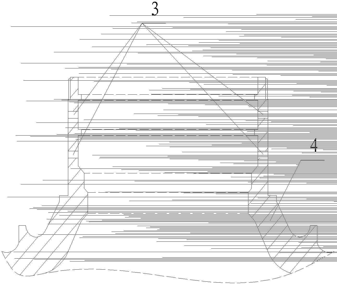
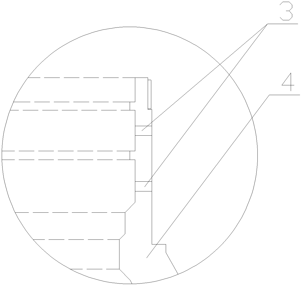
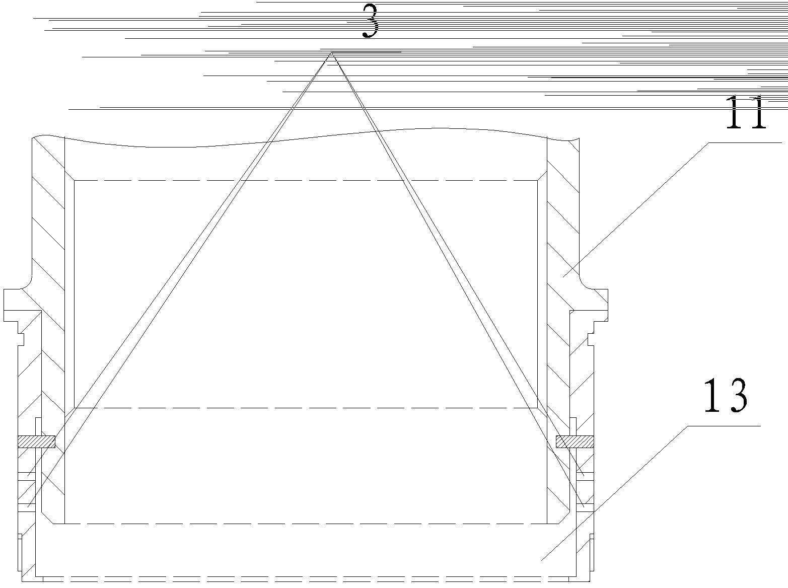
[0032] A method for flushing the oil supply hole under the rotor ring of a bearing that is lubricated by oil supply under the ring. The method for flushing the oil supply hole under the front journal ring in the oil supply hole under the ring is as follows: Figure 5 , Figure 6 shown, including the following steps:

[0033] Step 1: Place the front journal 4 to be flushed horizontally to ensure oil return collection;

[0034] Step 2: install an annular oil collection chamber 5 with an oil return port 9 on the inner side of the front journal 4;

[0035] Step 3: install an oil collector ring 6 with an oil inlet 10 on the outer side of the oil supply hole 3 under the ring of the front journal 4, and fix the oil collector ring 6 on the front journal 4 by pressing the nut 7;

[0036] Step 4: Connect the oil return port 9 of the annular oil collection chamber 5 with the oil return pipe 8 of the tester 12 (LS230), connect the oil inlet 10 of the oil collection ring 6 with the oil i...


PUM


Abstract

A method for flushing inner oil supply holes of a rotor of a bearing utilizing inner ring oil supply for lubricating belongs to the technical field of aviation engines and is capable of reducing rejection rate of bearings at the first fulcrum and the second fulcrum. The steps for flushing the inner oil supply holes of a front journal of the bearing include: placing the front journal horizontally and adding an annular oil collection cavity with an oil return port on the inner side of the front journal; adding an oil collection ring with an oil inlet outside the inner ring oil supply holes of the front journal and fixing the same onto the front journal through a hold-down nut; connecting the oil return port with an oil return pipe of a tester and connecting the oil inlet with an oil inlet pipe of the tester; starting the tester, heating oil to the temperature of 50-100DEG C and then pressurizing the same to 0.1-0.3Mpa, and setting flushing time within the range of 10min to 30min. The difference between the steps for flushing the inner oil supply holes of a back journal of the bearing and the steps for flushing the inner oil supply holes of the front journal of the bearing includes: a hold-down nut with an oil collection ring is additionally mounted outside the inner ring oil supply holes of the back journal, the annular oil collection cavity is fixed onto the back journal by the hold-down nut, an oil inlet is arranged on the hold-down nut and communicated with the oil collection ring.

Description

technical field [0001] The invention belongs to the technical field of aero-engines and gas turbines, and in particular relates to a method for flushing an oil supply hole under a rotor ring in which the bearing is lubricated by under-ring oil supply. Background technique [0002] Aeroengine bearing cleaning is an important part of the engine assembly process. Bearing cleaning can ensure the stable and long-term operation of the engine rotor; if the bearing is not clean, there may be failures such as shaft corrosion and shedding. faults, resulting in huge economic losses. [0003] The bearing adopts oil supply lubrication under the ring. The first and second fulcrum bearings of the engine are roller bearings, which are assembled on the low-pressure rotor assembly. The lubrication and oil supply method is oil supply through the oil supply hole under the ring. The structure of the bearing assembly is relatively complex, and the assembly is carried out after the single-piece c...

Claims


Application Information

Patent Timeline
Patent Type & Authority Patents(China)
IPC IPC(8): B08B3/02
Inventor 杜立峰可成河巩孟祥时金辉宋涛
Owner SHENYANG LIMING AERO-ENGINE GROUP CORPORATION
Why Eureka
Try Eureka