Expelling machine for aquatic animals
A technology for aquatic animals and power machines, applied in animal repellents, fishing, applications, etc., can solve problems such as low fish yield, difficult fishing, etc., to improve efficiency, reduce fishing costs, and be easy to use Effect
- Summary
- Abstract
- Description
- Claims
- Application Information
AI Technical Summary
Problems solved by technology
Method used
Image
Examples
Embodiment 1
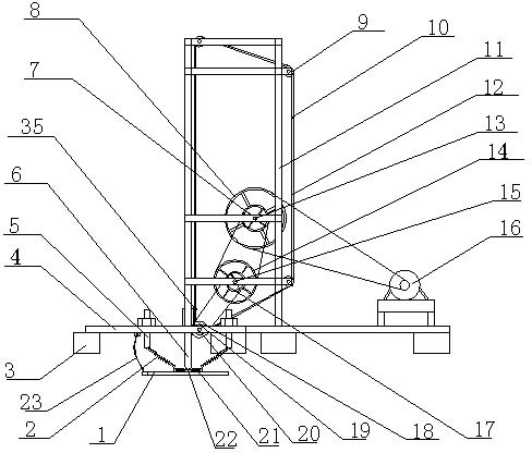
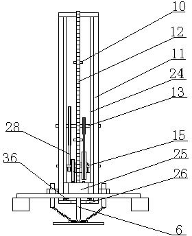
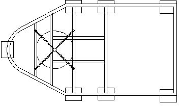
[0032] Such as figure 1 , figure 2 , image 3 and Figure 4 Shown, a kind of aquatic animal repelling machine, its frame 4 bottom is provided with vibrating plate 1 and floating ball 3, is provided with four lifting bolts 5 and nuts on frame 4, and vibrating plate 1 is connected with four springs 2 by four The lifting bolt 5 is connected, and the vibration plate 1 is equipped with an impact block 22. The impact block 22 is fixed on the vibration plate 1 with four small springs 21, and a protective rope 23 is installed between the vibration plate 1 and the frame 4, or on the vibration plate A guardrail is set below the 1 to prevent the vibrating plate 1 from being lost. Support 11 is installed on the frame 4, and the first transmission shaft 13, the second transmission shaft 15 and the third transmission shaft 20 are installed on the support 11, and the first transmission wheel 8 and the second transmission wheel are installed on the first transmission shaft 13 7. The thir...
Embodiment 2
[0035] Such as Figure 5 and Figure 6 As shown, a vibrating plate 1 and a floating ball 3 are arranged below the frame 4, four lifting bolts 5 and nuts are arranged on the frame 4, the vibrating plate 1 is connected with four lifting bolts 5 through four springs 2, and the vibrating plate 1 An impact block 22 is installed on it, and the impact block 22 is fixed on the vibrating plate 1 with four small springs 21. A protective rope 23 is installed between the vibrating plate 1 and the vibrating plate 1, or a guardrail is set below the vibrating plate 1 to prevent the vibrating plate from 1 is lost. Power machine 16 and lance 6 are installed on the frame 4, and power machine 16 is connected with speed reducer 29, and rotating disk 33 is installed on the output shaft of speed reducer 29, and the periphery of rotating disk 33 has striking tooth 34. The ram 6 has a ram 30 , and a return spring 31 is provided between the ram 30 and the frame 4 , and a guide tube 32 for guiding th...
Embodiment 3
[0037] Such as Figure 7 and Figure 8 As shown, the output shaft of the speed reducer 29 is connected with a crankshaft 37, the crankshaft 37 is equipped with a drum 38, and the drum 38 is symmetrically hinged with a movable connecting rod 39, and the movable connecting rod 39 is connected with the bumper 30 through a connecting spring 40 . Others are with embodiment 2.
PUM
 Abstract
Description
Claims
Application Information
 - R&D
- Intellectual Property
- Life Sciences
- Materials
- Tech Scout
- Unparalleled Data Quality
- Higher Quality Content
- 60% Fewer Hallucinations
Browse by: Latest US Patents, China's latest patents, Technical Efficacy Thesaurus, Application Domain, Technology Topic, Popular Technical Reports.
© 2025 PatSnap. All rights reserved.Legal|Privacy policy|Modern Slavery Act Transparency Statement|Sitemap|About US| Contact US: help@patsnap.com


