Image encoding device and image decoding device

An image encoding and image decoding technology, applied in the field of image decoding devices, can solve the problems of high computing load, reduced encoding efficiency, low encoding efficiency, etc., and achieve the effect of reducing the amount of code and improving the encoding efficiency

Inactive Publication Date: 2012-05-30
SHARP KK
View PDF9 Cites 5 Cited by
  • Summary
  • Abstract
  • Description
  • Claims
  • Application Information

AI Technical Summary

Problems solved by technology

Although this technology considers the characteristics of the transform coefficients, the motion vector estimation using the residual signal is only effective when there are too many transform coefficients.
[0030] In addition, since information obtained from transform coefficients is used to perform matching with a decoding device, the calculation load is extremely high
[0031] That is, in the existing coding technology, since the characteristics of the transform coefficients are not used to estimate the mode, the estimation accuracy of the mode is low and the coding efficiency is low
[0032] In addition, since the mode is not determined using the characteristics of the transform coefficients, even when the effect of mode switching is large, the encoding efficiency is reduced because the mode is limited to one estimated
[0033] In addition, even in the case where the effect of mode switching is small, the encoding efficiency is reduced due to the encoding of the flag used to identify the mode used

Method used


Image

  • Image encoding device and image decoding device
  • Image encoding device and image decoding device
  • Image encoding device and image decoding device

Examples


Embodiment approach 1

[0083] In Embodiment 1, the case where a scanning mode is selected and coded is demonstrated. In this case, the transform method and the quantization method are predetermined.

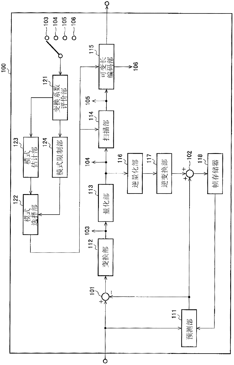
[0084] (Configuration of Image Coding Device 100 )

[0085] figure 1 It is a block diagram showing the configuration of the image coding device 100 according to Embodiment 1 of the present invention. exist figure 1 Among them, the image coding device 100 includes a prediction unit 111, a transformation unit 112, a quantization unit 113, a scanning unit 114, a variable length coding unit 115, an inverse quantization unit 116, an inverse transformation unit 117, a frame memory 118, a transformation coefficient evaluation unit 121, Mode selection unit 122 , mode estimation unit 123 , mode restriction unit 124 , subtraction unit 101 , and addition unit 102 . Reference numerals in the figure, 103 indicate the transform coefficient output from the transform unit 112, 104 indicate the quantized transform ...

Deformed example 1

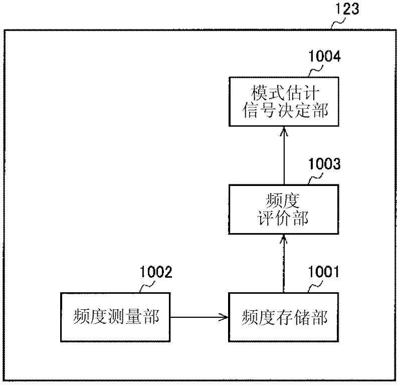
[0224] (A configuration including only the mode estimation unit 123)

[0225] Figure 10 It is a flowchart for explaining the operation of the mode selection unit 122 in Modification 1 that does not include the mode restriction unit 124 but includes the mode estimation unit 123 .

[0226] The operation of the mode selection unit 122 in this case is the same as using Figure 7The described situation is basically the same, but there are differences in that there is no S1009 operation of obtaining the mode restriction signal, S1010 decision / branch operation, and S1013 operation of setting the cost so that the scanning mode is not selected.

Deformed example 2

[0228] (A configuration including only the mode restricting unit 124)

[0229] Figure 11 It is a flowchart for explaining the operation of the mode selection unit 122 in Modification 2 in which the mode estimation unit 123 is not provided but the mode restriction unit 124 is provided.

[0230] The operation of the mode selection unit 122 in this case is the same as using Figure 7 The described situation is basically the same, but there is no difference in that there is no action of obtaining the mode estimation signal in S1008.

[0231] In addition, when the number of selectable scan modes is greater than one, the mode restricting unit 124 described above uses a list of mode numbers as selectable scan modes in addition to the number of selectable scan modes. However, in the case of Modification 2, even if the number of selectable scan modes is one, the range of selectable scan modes (here, one, Hence the scan mode).


PUM


Abstract

Disclosed is an image encoding device that aims to increase encoding efficiency and to increase mode estimation accuracy using the characteristics of transformation coefficients. In response to an assessment value calculated on the basis of the characteristics of transformation coefficients, the range of estimated modes and selectable modes is limited, a mode that minimizes encoding cost is selected from among predetermined modes within the limited range of modes, when the number of the aforementioned limited modes is one, a flag for mode identification is not encoded, and when there are a plurality of modes, the aforementioned selected mode is encoded. As a result, the amount of encoding cost of the mode-identifying flag is decreased and encoding can be performed with a high encoding efficiency, mode estimation accuracy is increased, and furthermore, the amount of flag encoding is decreased and encoding efficiency is increased.

Description

technical field [0001] The present invention relates to an image encoding device that encodes an image and outputs encoded data, and an image decoding device that decodes coded data encoded by the image encoding device. Background technique [0002] Image coding technology is used in a variety of peripheral video devices ranging from television receivers to mobile phones capable of image processing. [0003] In the technical field of image coding, image data (image information) is generally divided into a plurality of blocks, and encoding is performed in units of divided blocks. In encoding in units of blocks, the following processes are performed: generation of a predicted signal close to the input signal, calculation of a residual signal that is the difference between the input signal and the predicted signal, conversion of the calculated residual signal, Coding processing such as quantization of the obtained transform coefficients, scanning of the quantized transform coe...

Claims


Application Information

Patent Timeline
Patent Type & Authority Applications(China)
IPC IPC(8): H04N7/50
CPCH04N19/00781H04N19/00278H04N19/00157H04N7/50H04N7/26313H04N7/26244H04N19/00309H04N7/26127H04N7/26154H04N19/00018H04N7/26287H04N19/00545H04N7/26021H04N19/00175H04N19/103H04N19/14H04N19/147H04N19/176H04N19/184H04N19/46H04N19/61
Inventor 猪饲知宏
Owner SHARP KK
Why Eureka
Try Eureka