Fuel cell system
A technology of a fuel cell system and a fuel cell unit, which is applied in the direction of fuel cells, fuel cell additives, circuits, etc., and can solve problems such as the outflow of the water purifier 240, the reduction of water supply, and the obstruction of water supply to the reformer
- Summary
- Abstract
- Description
- Claims
- Application Information
AI Technical Summary
Problems solved by technology
Method used
Image
Examples
Embodiment approach 1
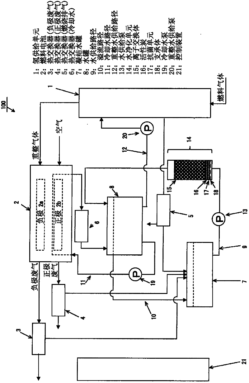
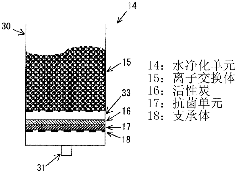
[0057] figure 1 It is a configuration diagram of the fuel cell system in the first embodiment of the present invention. figure 2 yes figure 1 The lower enlarged view of the cross-section of the water purification device included in the fuel cell system of . Such as figure 1 As shown, the fuel cell system 100 includes a hydrogen supply unit 1, a fuel cell unit (hereinafter simply referred to as "fuel cell") 2, heat exchangers 3-6, a condensed water tank 7, a water tank 8, a water supply path 9, and a control system. device 21 etc.
[0058] Among them, the hydrogen supply unit 1 reforms the fuel gas introduced from the outside of the system 100 into hydrogen-rich reformed gas, and supplies it to an anode 2 a of the fuel cell 2 . On the other hand, air humidified to an appropriate dew point is supplied from the outside to a cathode 2 b of the fuel cell 2 .
[0059] Condensed water is separated from anode off gas discharged from the anode 2 a of the fuel cell 2 in the hea...
Deformed example 1
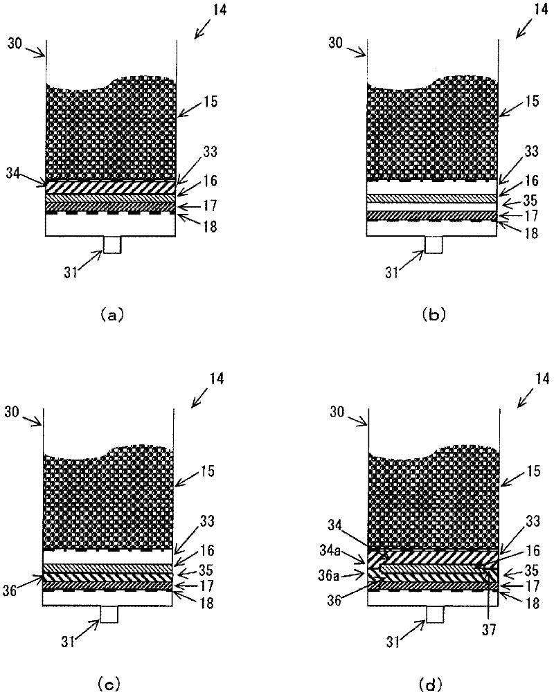
[0076] image 3 The water purification unit 14a shown in (a) and figure 2 The shown water purification unit 14 is mostly the same in structure, but differs in that the first spacer 34 is provided in the first gap portion 33 . The first separator 34 is formed flat using a material that cannot exchange ions, and water can flow therethrough. As such a material, for example, a resin member provided with a plurality of through holes, a porous resin member, woven fabric, or nonwoven fabric can be used.
[0077] With such a configuration, it is possible to securely secure the first gap portion 33 as a space having a predetermined capacity. In addition, in image 3 In (a), appended with figure 2 Parts marked the same as figure 2 The corresponding parts of the water purification unit 14 have the same structure, so their descriptions are omitted here ( image 3 The same applies to (b) to (d)).
Deformed example 2
[0079] image 3 The water purification unit 14b shown in (b) and figure 2 The shown water purification unit 14 has mostly the same structure, but has a second gap 35 between the activated carbon 16 and the antibacterial unit 17 in addition to the first gap 33 . With such a configuration, a large amount of water containing antibacterial ions can also be retained in the second gap portion 35 , so that the antibacterial agent can be more diffused around the activated carbon 16 .
PUM
 Abstract
Description
Claims
Application Information
 - R&D Engineer
- R&D Manager
- IP Professional
- Industry Leading Data Capabilities
- Powerful AI technology
- Patent DNA Extraction
Browse by: Latest US Patents, China's latest patents, Technical Efficacy Thesaurus, Application Domain, Technology Topic, Popular Technical Reports.
© 2024 PatSnap. All rights reserved.Legal|Privacy policy|Modern Slavery Act Transparency Statement|Sitemap|About US| Contact US: help@patsnap.com


