
Microfluidic device

A microfluidic device and microfluidic technology, applied in the field of microfluidic cytometer system, can solve problems such as low cell concentration

Inactive Publication Date: 2012-05-23
SONY CORP +1
View PDF7 Cites 13 Cited by
  • Summary
  • Abstract
  • Description
  • Claims
  • Application Information

AI Technical Summary

Problems solved by technology

Correspondingly, this results in a lower concentration of cells in the collection vessel of the fluid switching sorter compared to the collection vessel of the droplet sorter

Method used


Image

  • Microfluidic device
  • Microfluidic device
  • Microfluidic device

Examples


Embodiment Construction

[0048] In order to enhance the understanding of the principles of the invention, reference will now be made to the embodiments illustrated in the drawings, and specific language will be used to describe the same features. It should be understood, however, that no limitation of the scope of the invention is thereby intended, but alternatives and further modifications of the illustrated apparatuses and methods and the principles of the invention illustrated are intended to be protected as commonly understood by those skilled in the art to which the invention pertains further application.

[0049] Microfluidic device with data storage capability

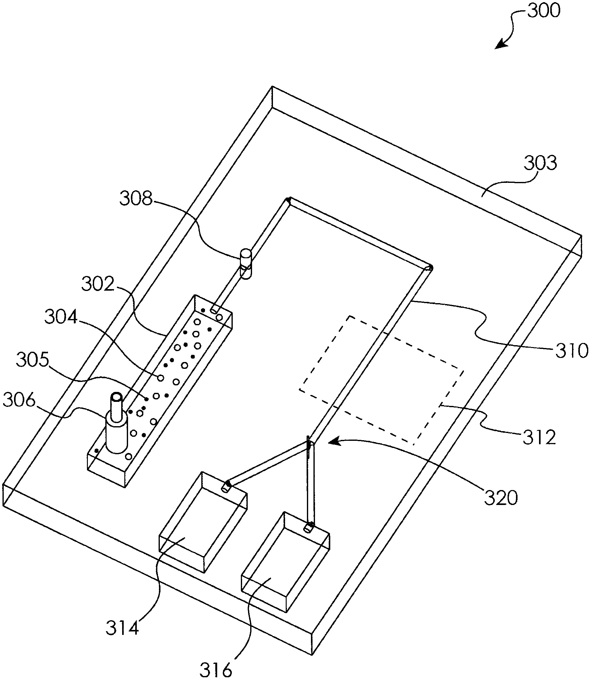
[0050] The present invention is generally directed to a system for storing and retrieving data on a microfluidic cytometry device, such as a cytometry chip. exist figure 2 In, a system 200 is schematically shown in which cells from an external cell source 202 are analyzed via a cytometer using microscopic cells formed onboard (i.e., ...


PUM


Abstract

The present disclosure relates to microfluidic devices adapted for facilitating cytometry analysis of particles flowing therethrough. In certain embodiments, the microfluidic devices have onboard data storage capabilities. In certain other embodiments, the microfluidic devices have onboard anticoagulants. In certain other embodiments, the microfluidic devices have onboard test and control channels. In certain other embodiments, the microfluidic devices have integrated collection media. In certain other embodiments, the microfluidic devices have multiple onboard test channels. In certain other embodiments, the microfluidic devices have localized temperature control. In certain other embodiments, the microfluidic devices have anatomy simulating regions. In certain other embodiments, the microfluidic devices have complete assay capabilities. In certain other embodiments, the microfluidic devices have dissociable sections. In certain other embodiments, the microfluidic devices have means for performing functional assays.

Description

[0001] Cross-References to Associated Applications [0002] This application claims priority to the following patent applications: U.S. Provisional Patent Application No. 61 / 223,415, filed July 7, 2009, U.S. Provisional Patent Application No. 61 / 223,411, filed July 7, 2009 , U.S. Provisional Patent Application No. 61 / 223,742 filed July 8, 2009, U.S. Provisional Patent Application No. 61 / 223,081 filed July 6, 2009, July 6, 2009 U.S. Provisional Patent Application No. 61 / 223,084 filed July 6, 2009, U.S. Provisional Patent Application No. 61 / 223,086 filed July 6, 2009, U.S. Provisional Patent Application No. 61 / 223,088 filed July 6, 2009 , U.S. Provisional Patent Application No. 61 / 223,085 filed July 6, 2009, U.S. Provisional Patent Application No. 61 / 223,405 filed July 7, 2009, July 7, 2009 US Provisional Patent Application No. 61 / 223,423 and US Provisional Patent Application No. 61 / 223,425 filed July 7, 2009, the entire contents of which are hereby incorporated by reference int...

Claims


Application Information

Patent Timeline
IPC IPC(8): G01N1/38
Inventor 加里·杜拉克
Owner SONY CORP
Learn More