Low-loss low-speed permanent magnet synchronous motor
A permanent magnet synchronous motor, low-loss technology, applied in synchronous motors with static armatures and rotating magnets, magnetic circuit rotating parts, magnetic circuit shape/style/structure, etc., can solve the problem of high harmonic electromotive force. Loss, inconvenient insertion of stator windings, and high copper consumption of the stator can improve assembly work efficiency, shorten the production period, and reduce wiring work.
- Summary
- Abstract
- Description
- Claims
- Application Information
AI Technical Summary
Problems solved by technology
Method used
Image
Examples
Embodiment 1
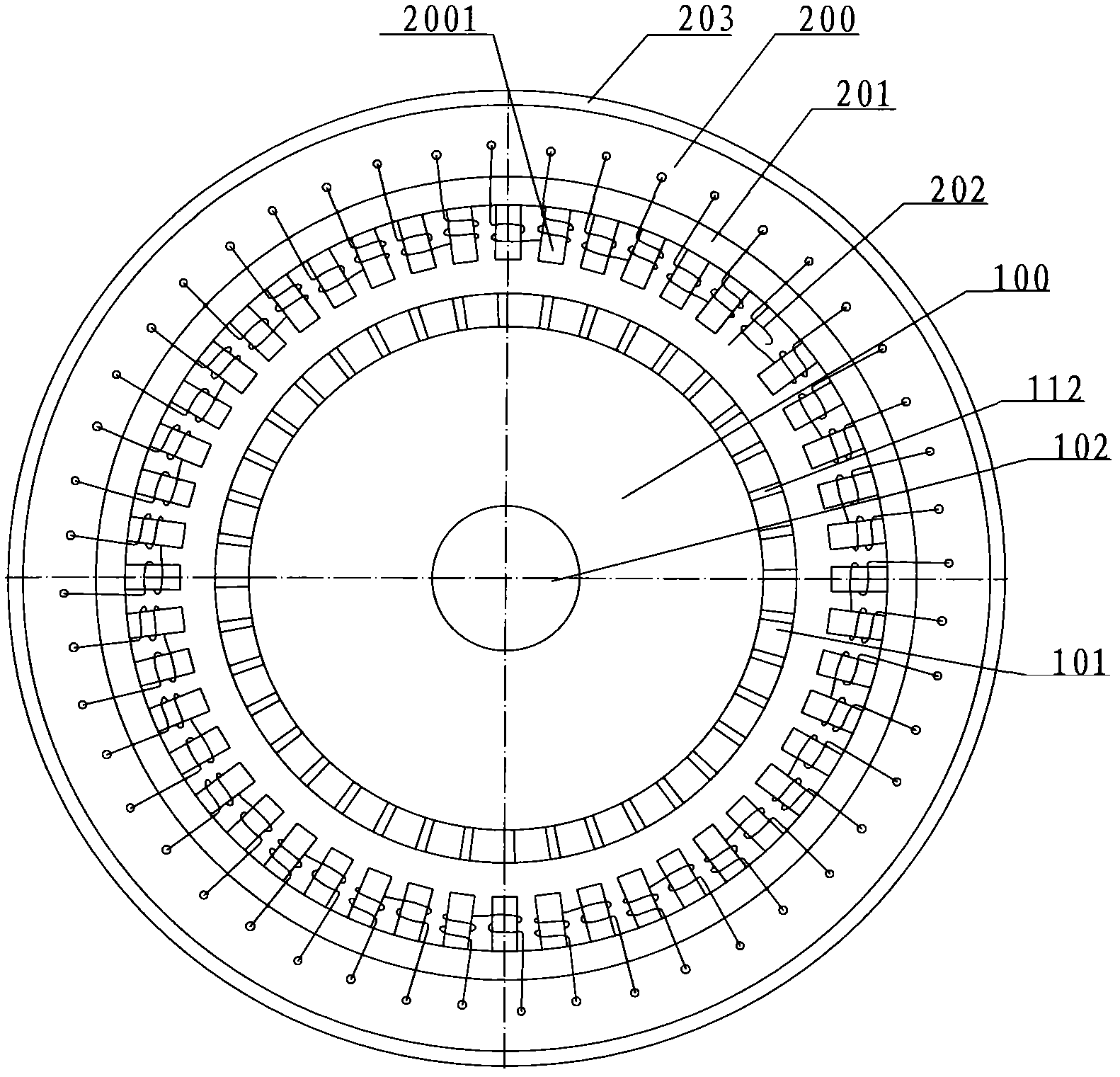
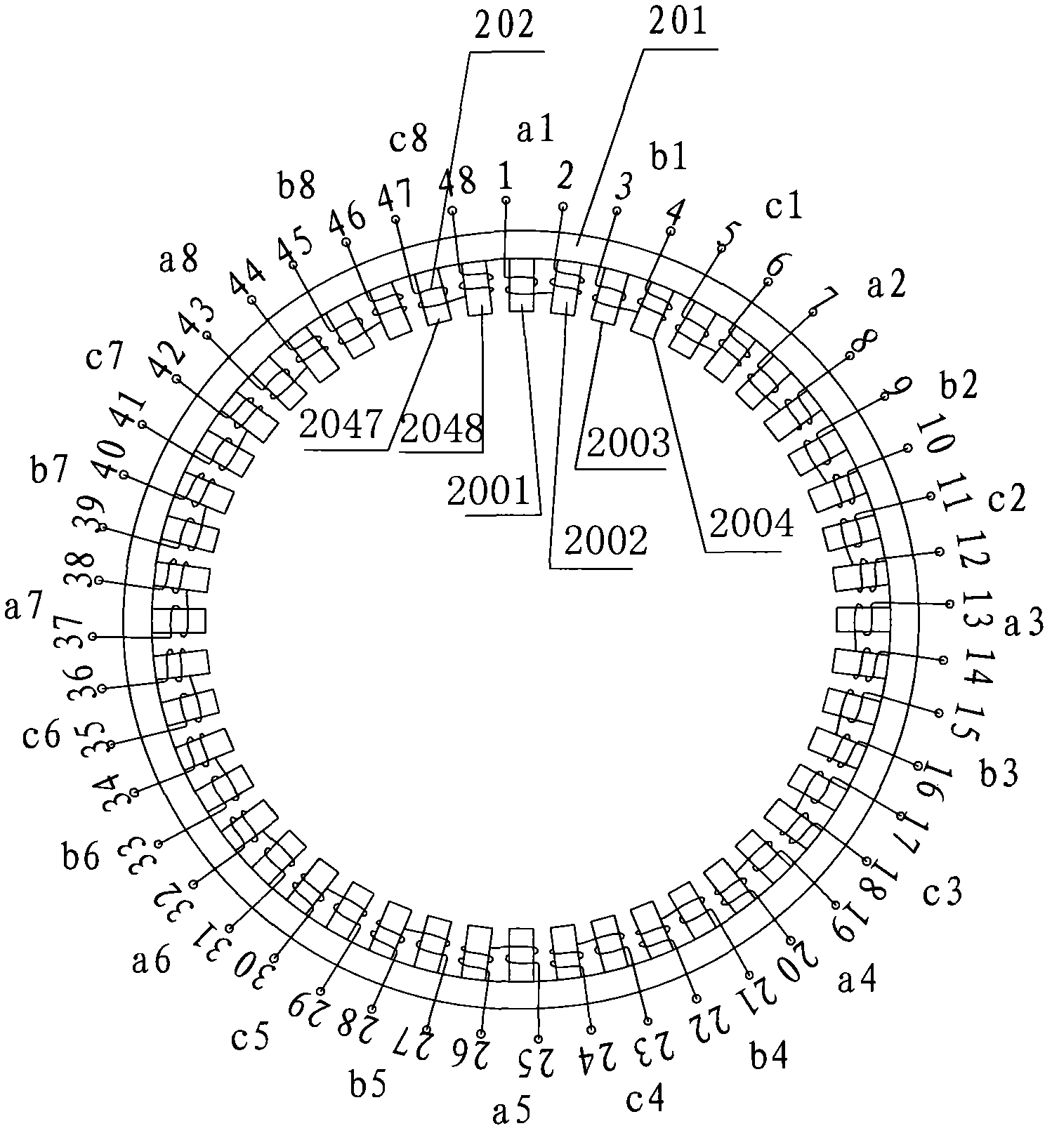
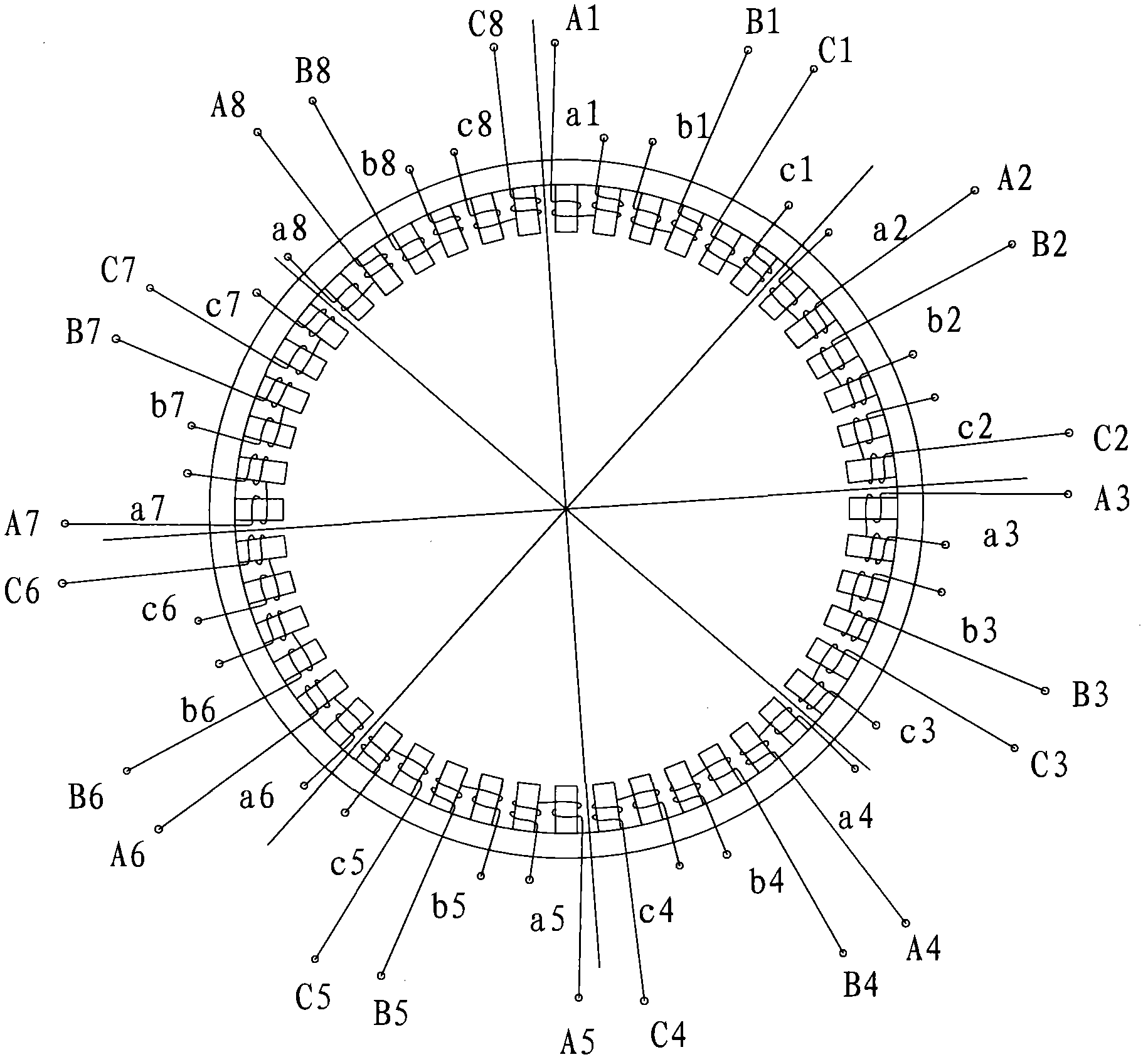
[0037] Embodiment one, see figure 1 , the figure shows a low-loss low-speed permanent magnet synchronous motor according to the present invention, which includes a rotor 100 and a stator 200, the stator 200 includes a casing 203, a stator core 201 and a stator winding 202, and the rotor 100 includes a rotor body 101 , rotating shaft 102, the motor pole slot ratio is 5:6, wherein the stator core 201 has 48 teeth 2001, 2002, ... 2048 ( figure 2shown), and there are 40 pairs of permanent magnets 112 on the surface of the rotor; for the stator structure, see figure 2 , including a stator core 201 and a stator winding 202. In this embodiment, the motor phase number m is 3, and the stator core 201 has teeth 2001, 2002, 2003..., 2047, 2048 for coil nesting, and the number of teeth is 48. S=2nm, n is 8; each phase winding is composed of a coil unit, in the present invention, the coil unit a1 is a single-tooth half winding with the same winding direction on two adjacent teeth (for e...
Embodiment 2
[0045] Embodiment two, see Figure 7 , the figure shows the same as that of Example 1 image 3 Different stator winding connection methods shown in : connect the first group of three-phase winding units (a1, b1, c1) and the second group of three-phase winding units (a2, b2, c2) in series among the eight three-phase winding units, The third group of three-phase winding units (a3, b3, c3) and the fourth group of three-phase winding units (a4, b4, c4) are connected in series, the fifth group and the sixth group are connected in series, the seventh group and the eighth group are connected in series, and so on Constitute four sets of independent three-phase windings. combine figure 2 and Figure 7 , taking the first group as an example to illustrate its connection method. For clarity of description, the left end of the coil unit a1 is defined as the head end, and the right end is defined as the end, and the adjacent end of the coil unit b1 and a1 is defined as the head end, an...
Embodiment 3
[0046] Embodiment three, see Figure 8 , the figure shows the same as that of Example 1 image 3 and embodiment two Figure 7 Different stator winding connection methods shown in : connect the first, second, third, and fourth sets of three-phase winding units (a1, b1, c1), (a2, b2, c2), (a3, b3, c3); (a4 , b4, c4) are connected in series as an independent three-phase winding (A1, B1, C1), and the fifth, sixth, seventh, and eighth three-phase winding units (a5, b5, c5), (a6, b6, c6 ), (a7, b7, c7); (a8, b8, c8) are connected in series to form an independent three-phase winding (A2, B2, C2); take the first three-phase winding (A1, B1, C1) as an example : In the three-phase winding unit (a1, b1, c1), the head end of the coil unit a1, the end of b1, and the head end of c1 are respectively connected to the leading end, and the end of a1 is connected to the three-phase winding unit (a2, b2, c2) The end of the coil unit a2; the head end of the coil unit b1 is connected to the head...
PUM
 Abstract
Description
Claims
Application Information
 - Generate Ideas
- Intellectual Property
- Life Sciences
- Materials
- Tech Scout
- Unparalleled Data Quality
- Higher Quality Content
- 60% Fewer Hallucinations
Browse by: Latest US Patents, China's latest patents, Technical Efficacy Thesaurus, Application Domain, Technology Topic, Popular Technical Reports.
© 2025 PatSnap. All rights reserved.Legal|Privacy policy|Modern Slavery Act Transparency Statement|Sitemap|About US| Contact US: help@patsnap.com


