
Sealed master cylinder and plunger of vehicle hydraulic-brake system

A technology of hydraulic braking and sealing structure, applied in the direction of engine sealing, brake actuator, brake, etc., can solve the problems of fluid obstruction, return oil flow path obstruction, unable to form return oil flow path, etc., to reduce the The effect of impedance

Active Publication Date: 2012-05-23
陈德三
View PDF10 Cites 2 Cited by
  • Summary
  • Abstract
  • Description
  • Claims
  • Application Information

AI Technical Summary

Problems solved by technology

Please refer to Figure 9 As shown, the prior art shows that the sealing collar 41 mainly includes a ring body 410, which defines the inner and outer sides of the ring body 410 in the same direction as the axial direction, and defines the top and bottom sides and the diameter of the ring body 410. The direction is the same direction; a first ring wall 411 and a second ring wall 412 are protruded inwardly along the ring body 410, by Figure 9 Observationally, it shows that the first ring wall 411 of the prior art is adjacent to the side wall 441 of the receiving groove 44, which is in dense and thick contact, and cannot form an oil return flow path, so it only affects the pressure relief fluid in the cylinder. It can flow to the reciprocating space 47 of the plunger 43 through the deformation of the second ring wall 412 along the gap 46 between the plunger 43 and the master cylinder 42, which obviously forms a large resistance to the oil return flow path. suffocate
[0004] and Figure 10 Shown is the prior art 2 of U.S. Patent No. USP7,401,468, which is also provided with a first ring wall 511 and a second ring wall 512, and a ring wall 513 is further protruded between the two ring walls, although the first ring wall The wall 511 is adjacent to the side wall 541 of a receiving groove 54, which is slightly arc-shaped to reduce the contact area and suffocation, and can form an oil return flow path, but the second ring wall 512 and the plunger surface 531 of the plunger 53 are the same It is also dense and thick contact, which cannot form an oil return flow path, so the pressure relief oil return fluid can only follow the gap 56 between the first ring wall 511 and the side wall 541 of a receiving groove 54, through the first The deformation of the ring wall 511, flowing to the reciprocating space 55 of the plunger 53, still forms a large obstruction
[0005] Other Figure 11 Shown is the prior art 3 of U.S. Patent No. USP7,600,761, which is also provided with a first ring wall 611 and a second ring wall 612, and a ring wall 613 is further protruded between the two ring walls. The walls 611 are respectively adjacent to the side walls 641 of a receiving groove 64, and the second ring wall 612 is also in dense and thick contact with the plunger surface 631 of the plunger 63, so an oil return flow path cannot be formed, so the pressure is released and the oil is returned. The fluid can only flow to the reciprocating space of the plunger 63 along the gap 66 between the first ring wall 611 and the side wall 641 of a receiving groove 64 through the deformation of the first ring wall 611, and it still has no impact on the leakage. The high-pressure fluid forms a large blockage on the oil return flow path

Method used


Image

  • Sealed master cylinder and plunger of vehicle hydraulic-brake system
  • Sealed master cylinder and plunger of vehicle hydraulic-brake system
  • Sealed master cylinder and plunger of vehicle hydraulic-brake system

Examples


Embodiment Construction

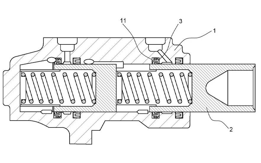
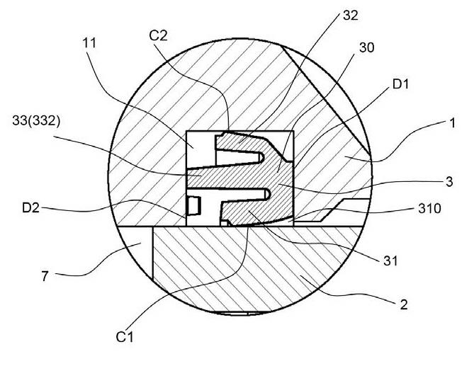
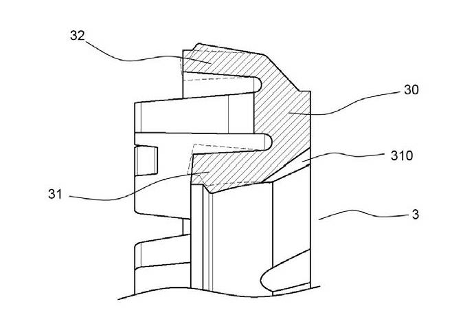
[0020] see figure 1 , please cooperate with the detailed diagram figure 2 , 3 As shown, the seal structure between the master cylinder and the plunger of the vehicle hydraulic braking system of the present invention includes a master cylinder 1 and a plunger 2 adjacent to each other, and the master cylinder 1 is provided with an accommodating cylinder adjacent to the plunger 2 Groove 11; and a sealing collar 3 is set, and the sealing collar 3 is arranged in the receiving groove 11, and the sealing collar 3 cooperates with the material characteristics and the tightness of the structure and assembly, so as to limit the passage of the fluid around the plunger 2 . And under the dynamic reciprocating action of the plunger 2, it can also be affected by the action of the plunger 2, and the fluid (such as brake oil) that allows pressure relief can be deformed by the sealing collar 3 (for the deformation state, please refer to image 3 ) through the two oil paths generated. That ...


PUM


Abstract

A sealed master cylinder and plunger of a vehicle hydraulic-brake system, includes a master cylinder, a plunger and a seal collar. The master cylinder is adjacent the plunger and has a holding slot disposed thereon and adjacent the plunger, and the seal collar provided in the holding slot. The seal collar comprises a collar body, separated into a circumferential inner wall and a circumferential outer wall, both of which are pliable. The sealed master cylinder and plunger further comprises a first fluid passage formed between the circumferential inner wall and the plunger and a second fluid passage formed between the circumferential outer wall and the holding slot.

Description

technical field [0001] The invention relates to a sealing structure of a master cylinder and a plunger, especially the structure of a master cylinder and a plunger used in a vehicle hydraulic braking system. Background technique [0002] The master cylinder and plunger seal structure of a general vehicle hydraulic brake system usually includes a master cylinder and a plunger, and a receiving groove is provided at the place where the master cylinder body and the plunger are adjacent to accommodate the sealing collar. place. The sealing collar cooperates with the material properties and the compactness of the structure and assembly to restrict the passage of the fluid around the plunger. Under the dynamic reciprocating action of the plunger, it can also be affected by the action of the plunger, allowing the fluid (such as brake oil) to generate pressure buildup and pressure release due to spatial changes, especially through the deformation of the sealing collar The path is f...

Claims


Application Information

Patent Timeline
IPC IPC(8): F16D65/14F16J15/16
CPCF16D65/14B60T11/232F16J15/16B60T11/236
Inventor 陈德三
Owner 陈德三
Learn More