Light emitting diode (LED) finger ring

A technology of rings and induction coils, which is applied in the field of LED rings, can solve the problems of poor color, high price, easy wear of the gold-plated layer, etc., and achieve the effect of enhancing the sense of appearance

Inactive Publication Date: 2012-05-23
XIAN COMEN ELECTRONICS TECH
View PDF0 Cites 4 Cited by
  • Summary
  • Abstract
  • Description
  • Claims
  • Application Information

AI Technical Summary

Problems solved by technology

Each of these rings has its corresponding advantages and disadvantages. Pure gold rings are relatively high-end, but expensive; gold-plated rings are affordable, but the gold-plated layer is easy to wear; brass rings are cheap, but the color is poor

Method used


Image

  • Light emitting diode (LED) finger ring
  • Light emitting diode (LED) finger ring

Examples


Embodiment Construction

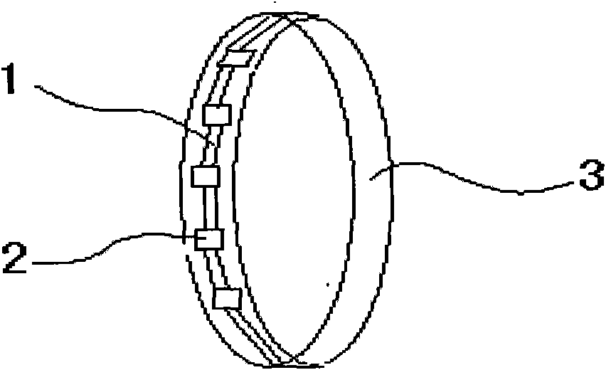
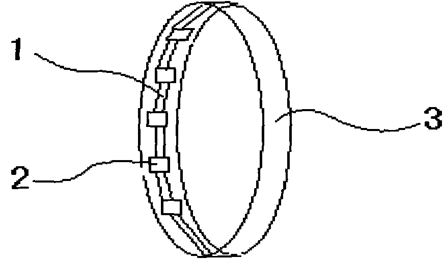
[0009] An LED ring mainly includes an induction coil 1, an LED light-emitting chip 2, and a ring 3; wherein the induction coil 1 is connected in series with the LED light-emitting chip 2, and is attached to the ring 3; wherein the induction coil 1 is a radio frequency IC card induction coil, and the ring 3 is a diamond ring, a gemstone ring, a platinum ring, a gold ring, and a silver ring; in this invention, when talking on a mobile phone or having electromagnetic waves, the induction coil 1 generates an oscillating current to light up the LED chip, and the ring 3 will flash and shine, leading the trend.


PUM


Abstract

The invention discloses a light emitting diode (LED) finger ring, which mainly comprises an induction coil, an LED luminous chip and a finger ring. The LED finger ring is characterized in that: the induction coil is connected in series with the LED luminous chip and attached to the finger ring, wherein the induction coil is a radio frequency integrated circuit (IC) card induction coil; the finger ring is a diamond ring, a gemstone ring, a platinum ring, a gold ring or a silver ring; and when a mobile phone is communicated or electromagnetic wave exits, the finger ring flashes so as to lead tide. The invention has the technical advantages that the LED finger ring is fashionable, attractive and simple in structure.

Description

technical field [0001] The invention belongs to the technical field of jewelry supplies, and in particular relates to an LED ring. Background technique [0002] Rings are one of the most common jewelry in people's daily life. There are many types of rings. In terms of composition, there are pure gold rings, gold-plated rings, and brass rings. Each of these rings has its corresponding advantages and disadvantages. Pure gold rings are relatively high-end, but expensive; gold-plated rings are affordable, but the gold-plated layer is easy to wear; However, setting a colored LED light on the outer surface of the ring will make the ring more fashionable and aesthetically pleasing. Contents of the invention [0003] The object of the present invention is to provide an LED ring aiming at the shortcomings of the prior art, which is a ring with low price, beautiful appearance, simple structure, high grade and not easy to wear. [0004] The technical scheme adopted in the present i...

Claims


Application Information

Patent Timeline
Patent Type & Authority Applications(China)
IPC IPC(8): A44C9/00F21V33/00H05B37/02F21Y101/02
Inventor 薛向令郑健
Owner XIAN COMEN ELECTRONICS TECH
Why Eureka
Try Eureka