Circuit diagram rewiring method

A technology of rewiring and circuit diagrams, applied in the direction of electrical digital data processing, special data processing applications, instruments, etc., can solve problems such as signal transmission errors, different signal delay times, different delay times, etc., and achieve the effect of avoiding different transmission times

Active Publication Date: 2012-05-16
高邮市驿都小微企业服务管理有限公司
View PDF4 Cites 2 Cited by
  • Summary
  • Abstract
  • Description
  • Claims
  • Application Information

AI Technical Summary

Problems solved by technology

Therefore, if the paired signal wires 120 and 130 are wired on the substrate 110 in a direction parallel to the weft wire 112 (such as figure 1 As shown), the paired signal lines 120 and 130 will be affected by the uneven surface when transmitting the paired signal, and have different delay times
In addition, in other examples, if the paired signal lines 120 and 130 are routed on the substrate 110 parallel to the warp line 111, the paired signal lines 120 and 130 will also have different delays when transmitting the paired signals. time
In today's situation where the signal speed is getting faster and faster, the delay time of the paired signals is different and it is easy to cause signal transmission errors

Method used


Image

  • Circuit diagram rewiring method
  • Circuit diagram rewiring method
  • Circuit diagram rewiring method

Examples


Embodiment Construction

[0027] The following will clearly illustrate the spirit of the present invention with the accompanying drawings and detailed descriptions. After any person with ordinary knowledge in the art understands the preferred embodiments of the present invention, he can change and modify it by the technology taught in the present invention. without departing from the spirit and scope of the present invention.

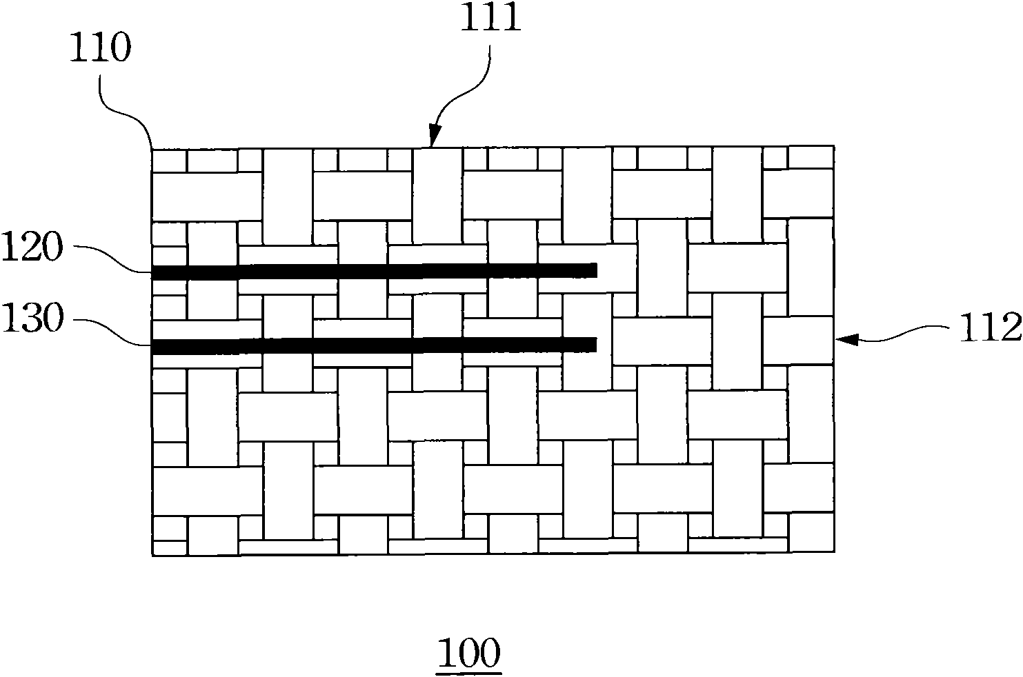
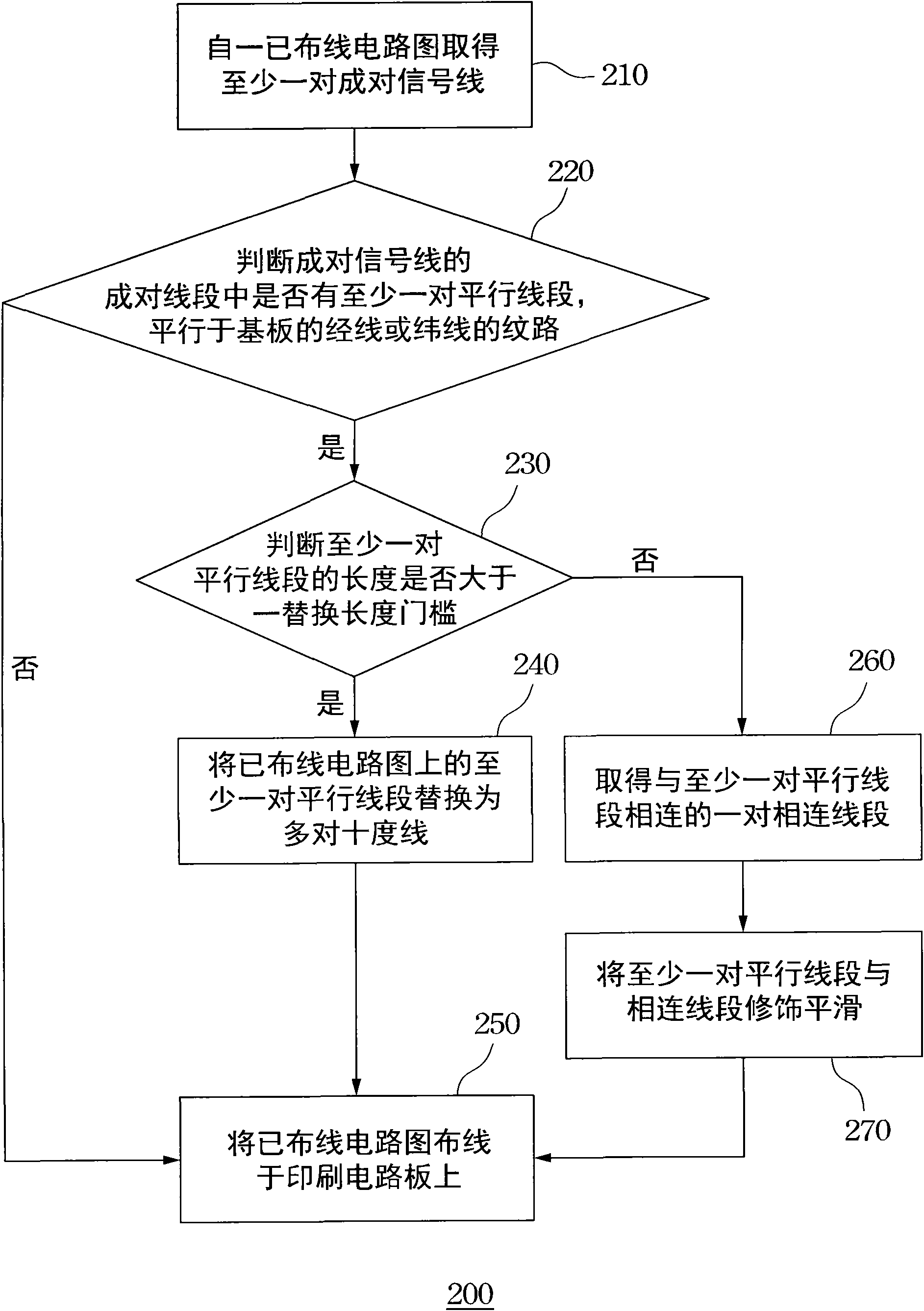
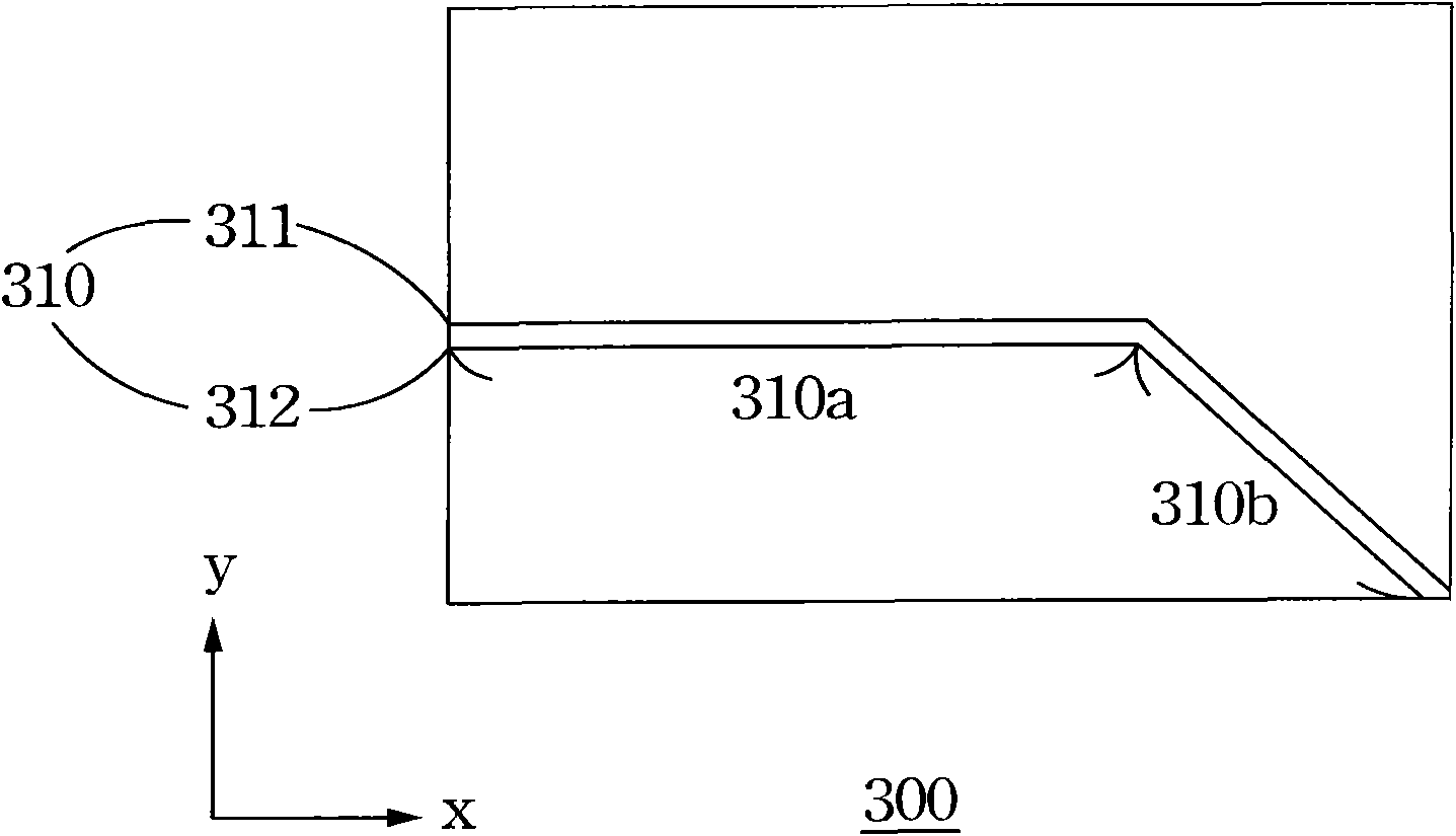
[0028] figure 2 It is a flowchart of a circuit diagram rewiring method according to an embodiment of the present invention. Figure 3A-3B It shows the flow of ten-degree line replacement for a wired circuit diagram. Figure 4 is an embodiment of a printed circuit board. The circuit diagram rerouting method is used for rerouting the routed circuit diagram, so that the redistributed circuit diagram is arranged on a substrate of a printed circuit board. Further, the circuit diagram rerouting method is to use multiple pairs of ten-degree lines to replace the pairs of signal line...


PUM


Abstract

The invention provides a circuit diagram rewiring method comprising the following steps of: obtaining at least one pair of paired signal wires from a circuit diagram wired previously, wherein the circuit diagram wired previously is laid on a substrate of a printed circuit board; the substrate is provided with a plurality of warps and a plurality of wefts; the at least one pair of paired signal wires includes two signal wires parallel to each other; and the paired signal wires include a plurality of pairs of paired segments; determining whether there is at least one pair of parallel segments among the paired segments which is parallel to the warp or the weft; and if there is at least one pair of parallel segments, replacing at least one pair of parallel segments on the circuit diagram wired previously by a plurality of pairs of ten-degree wires, wherein the ten-degree wire forms an angle of ten degrees with the warp or the weft.

Description

technical field [0001] The present invention relates to a wiring method, and more particularly to a circuit diagram rewiring method. Background technique [0002] In order to simplify the production of electronic machines, reduce the wiring between electronic parts, and reduce production costs, people began to study the method of replacing wiring with printing, thus producing printed circuit boards (Printed Circuit Board, PCB), or called It is a printed circuit board (Printed Wire Board, PWB). Printed circuit boards are important electronic components used to provide circuit connections for electronic components. Among them, the traditional circuit board adopts the method of printing etch resist to make the circuit line and picture surface, so it is called printed circuit board or printed circuit board. Due to the continuous miniaturization and refinement of electronic products, most of the current circuit boards are made by attaching etch resist (lamination or coating), a...

Claims


Application Information

Patent Timeline
IPC IPC(8): G06F17/50
Inventor 谢祥毅
Owner 高邮市驿都小微企业服务管理有限公司
Why Eureka
Try Eureka