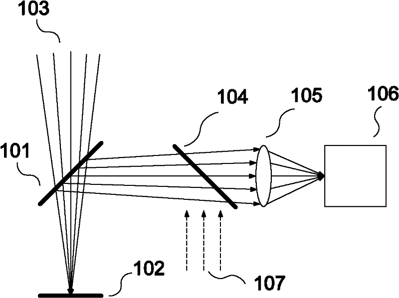
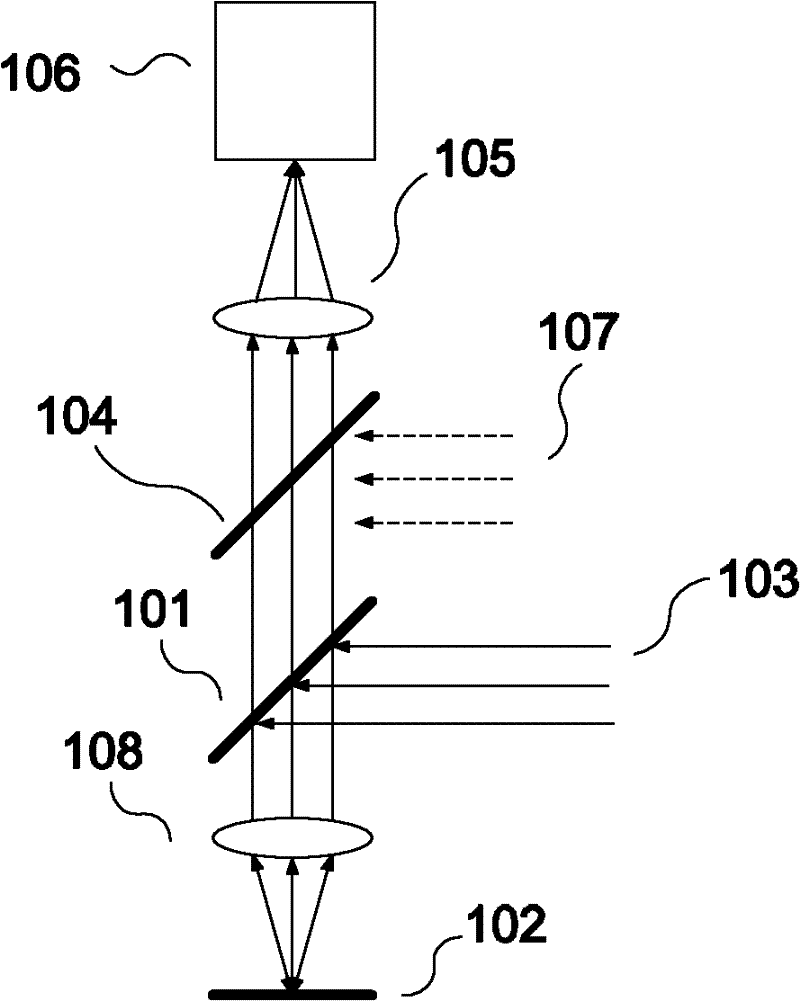
Imaging system using plane mirror to integrate lights and optical measuring device
A flat mirror and imaging system technology, applied in the field of optical measurement, can solve the problems of high cost, chromatic aberration, polarization state change, etc., and achieve the effect of low cost and simple structure
- Summary
- Abstract
- Description
- Claims
- Application Information
AI Technical Summary
Problems solved by technology
Method used
Image
Examples
Embodiment 1
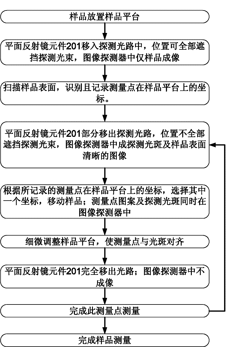
[0044] Such as Figure 3b As shown, the imaging system of this embodiment includes: a first movable mirror 201 , a sample 202 , a detection beam 203 , a beam splitter 204 , an imaging focusing unit 205 , an image detector 206 and an illumination beam 207 . The flowchart of this embodiment consists of Figure 3a Shown, the specific technical scheme of its key steps is as follows:
[0045] When measuring point identification and positioning, such as Figure 3b As shown, the first movable reflector 201 moves into the detection beam 203, and the detection beam 203 is completely incident on the non-reflective surface of the first movable reflector 201 and is completely blocked; after the illumination beam 207 is reflected by the beam splitter 204, it is incident on the The reflective surface of the first movable mirror 201 is reflected by the first movable mirror 201 and illuminates the surface of the sample 202 (the optical path is not shown). The reflected light beam 207 on th...
Embodiment 2
[0053] Such as Figure 4b As shown, the imaging system of this embodiment includes: a second movable mirror 201 ′, a first movable mirror 201 ″, a sample 202 , a detection beam 203 , an imaging focusing unit 205 , an image detector 206 and an illumination beam 207 . The flowchart of this embodiment consists of Figure 4a Shown, the specific technical scheme of its key steps is as follows:
[0054] When measuring point identification and positioning, such as Figure 4b As shown, the second movable mirror 201' moves into the optical path of the reflected beam of the probe beam 203 on the surface of the sample 202. The first movable mirror 201" moves into the detection beam 203 (the dotted line position), and the detection beam 203 is completely incident on the non-reflective surface of the first movable mirror 201", and is completely blocked. The illuminating beam 207 is reflected by the first movable mirror 201 ″, and irradiates the surface of the sample 202; the reflected l...
PUM
| Property | Measurement | Unit |
|---|---|---|
| thickness | aaaaa | aaaaa |
| thickness | aaaaa | aaaaa |
Abstract
Description
Claims
Application Information
 - Generate Ideas
- Intellectual Property
- Life Sciences
- Materials
- Tech Scout
- Unparalleled Data Quality
- Higher Quality Content
- 60% Fewer Hallucinations
Browse by: Latest US Patents, China's latest patents, Technical Efficacy Thesaurus, Application Domain, Technology Topic, Popular Technical Reports.
© 2025 PatSnap. All rights reserved.Legal|Privacy policy|Modern Slavery Act Transparency Statement|Sitemap|About US| Contact US: help@patsnap.com


