
Dynamic contact resistance testing device of conducting ring

A technology of dynamic contact resistance and test device, applied in the field of conductive rings, can solve the problems of low test accuracy, inability to carry out continuous dynamic test, low efficiency, etc., and achieve the effect of reducing human factors, improving work efficiency and test accuracy, and reasonable design.

Inactive Publication Date: 2012-05-09
中国船舶重工集团公司第七〇七研究所
View PDF2 Cites 16 Cited by
  • Summary
  • Abstract
  • Description
  • Claims
  • Application Information

AI Technical Summary

Problems solved by technology

The main performance indicators of power transmission devices are contact resistance and friction torque. At present, the dynamic test method for contact resistance mainly uses digital milliohmmeters for manual testing. The existing problems are: 1. The test accuracy is low, and it can only be applied to High power transmission device; 2. Continuous dynamic testing cannot be performed, and its efficiency is low

Method used


Image

  • Dynamic contact resistance testing device of conducting ring
  • Dynamic contact resistance testing device of conducting ring
  • Dynamic contact resistance testing device of conducting ring

Examples


Embodiment Construction

[0012] Embodiments of the present invention are described in further detail below in conjunction with the accompanying drawings:

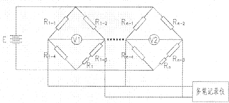
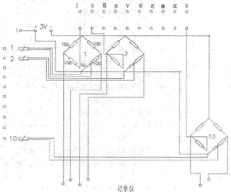
[0013] The utility model relates to a dynamic contact resistance testing device of a conductive ring, which is realized by testing based on the principle of an electric bridge. The testing principle of the present invention is as figure 1 As shown, the test circuit consists of a standard resistor R of the same resistance 1-1 , R 1-2 …R n-1 , R n-2 Form stable N bridges, according to the principle of the bridge, the output voltage V at this time 1 , V 2 …V N is zero, and each contact resistance R of the power transmission device (conductive ring) 1 …R n After each bridge is introduced separately, the balance of each bridge is destroyed, and the output voltage V of each bridge 1 , V 2 …V N Sampling and recording can be carried out by multiple recorders, and finally the recorded voltage value can be calculated through the bridge balance the...


PUM


Abstract

The invention relates to a dynamic contact resistance testing device of a conducting ring, and the dynamic contact resistance testing device is mainly and technically characterized by comprising a voltage stabilization constant current source, bridges formed by precision resistors, adjustable resistors used for fine adjusting the bridges, and a multi-pen recorder, wherein the voltage stabilization constant current source is connected with input ends of the bridges to supply power to the whole testing device; voltage output ends of the bridges are connected with the multi-pen recorder which is used for recording output voltages of the bridges; the adjustable resistors are respectively connected in series onto a bridge arm of the bridges; one end of the power output device is connected onto one end of the voltage stabilization constant current source; and the other end of the power output device is connected with the inner parts of the bridges to form a testing loop. The dynamic contact resistance testing device has a reasonable design, multiple ways of bridges and the multi-pen recorder are adopted by the dynamic contact resistance testing device to dynamically test contact resistance in the power output device, human factors in the testing process are reduced, a function of continuous and automatic testing is performed, the working efficiency and the testing precision are improved, and the dynamic contact resistance testing device can be widely used in the field of the testing of the dynamic contact resistance of the conducting ring.

Description

technical field [0001] The invention belongs to the field of conductive rings, in particular to a dynamic contact resistance testing device for conductive rings. Background technique [0002] Conductive rings have been widely used in aviation, aerospace, navigation and precision instruments. The conductive ring can realize the signal transmission between two relatively rotating parts. It can also be said that the transmission of electrical signals between any relative rotating parts can be completed by using the conductive ring. The main performance indicators of power transmission devices are contact resistance and friction torque. At present, the dynamic test method for contact resistance mainly uses digital milliohmmeters for manual testing. The existing problems are: 1. The test accuracy is low, and it can only be applied to High power transmission device; 2. Continuous dynamic test cannot be carried out, and its efficiency is low. Contents of the invention [0003] ...

Claims


Application Information

Patent Timeline
Patent Type & Authority Applications(China)
IPC IPC(8): G01R27/02
Inventor 张缨徐凯张群刘伟
Owner 中国船舶重工集团公司第七〇七研究所
Learn More