Electric shifting wheel hub with sliding stopper
An electric wheel hub and blocker technology, applied in the field of wheels, can solve problems such as threats to driving safety
- Summary
- Abstract
- Description
- Claims
- Application Information
AI Technical Summary
Problems solved by technology
Method used
Image
Examples
Embodiment 1
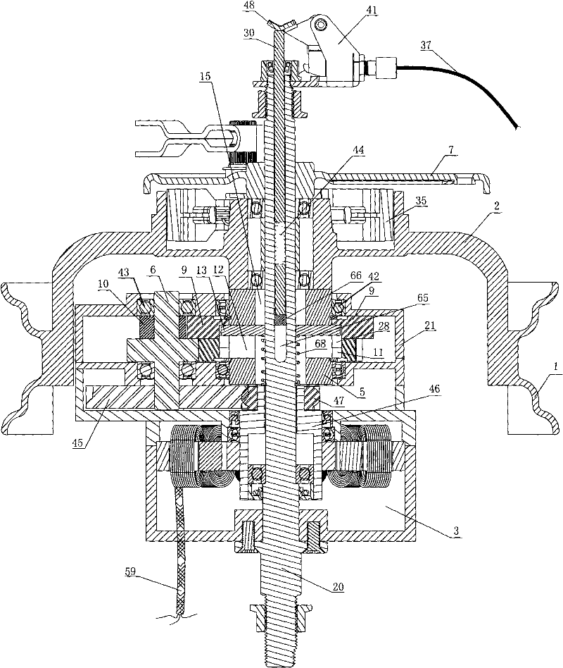
[0029] Such as figure 1 As shown in , the sliding gear variable speed electric hub includes a hub ring 1, the hub ring 1 is connected with an end face 2, the end face 2 is connected with the hollow output shaft 5, and a shaft hole 15 of the hollow output shaft 5 is provided with a Root integral solid supporting shaft 20. An integral solid support shaft 20 is not only convenient for manufacturing and processing, but also convenient for assembly. Compared with the hollow support shaft provided with a power line hole, it has good rigidity and supporting strength.
[0030] The motor 3 is fixed on the support shaft 20, and the power cord 59 of the motor 3 directly stretches out from the casing of the motor. The motor 3 is fixed on the support shaft 20, and the motor shaft gear 47 is arranged on the outer end of the motor shaft 46. The motor 3 is fixed with a gearbox body 21, and the gearbox body 21 can be fixed on the shell of the motor 3, or can be made into an integral structur...
Embodiment 2
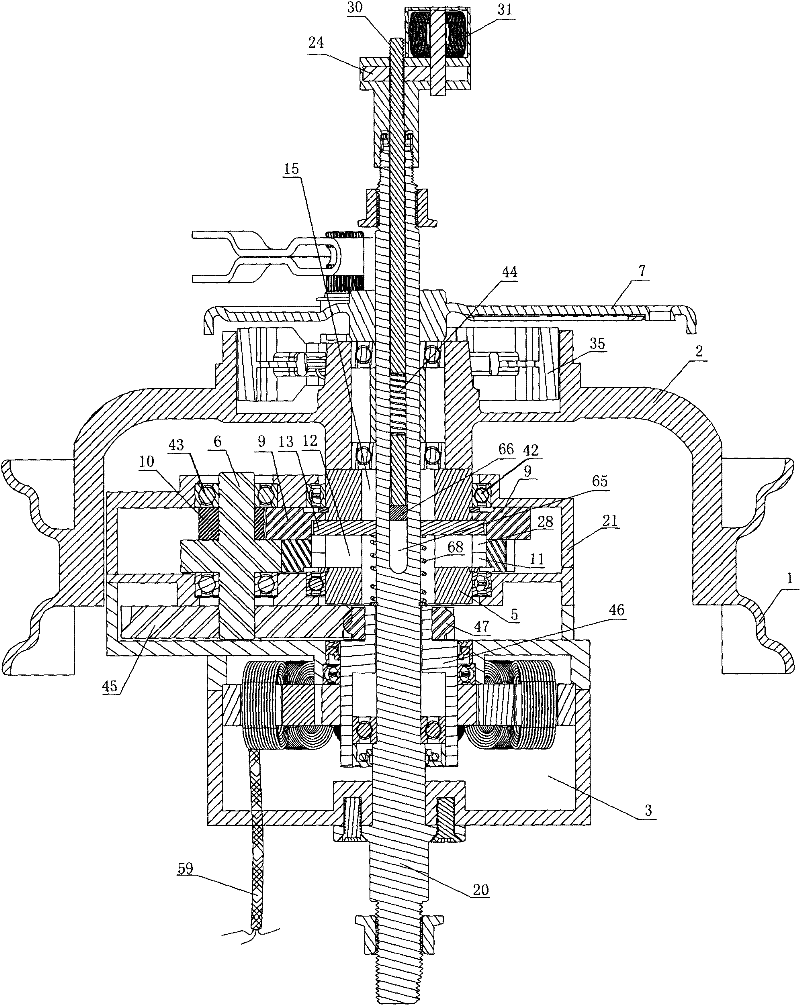
[0037] The axial end of the retainer 13 is in contact with a clip 66, and the adjustment rod 30 is connected to the clip 66. The other end of the adjustment rod 30 is provided with a screw 4, and the screw 4 is connected to the threaded hole 26 on the internally threaded gear 24. Cooperate, when the stepper motor 31 fixed on the support shaft 20 rotates, it drives the inner screw gear 24 to rotate, and when the inner screw gear 24 rotates, the adjustment rod 30 is pushed or pulled to move in the shaft hole 15, and the stopper 13 is driven to move in the shaft hole 15. middle movement, the other end of the stopper 13 is provided with a return spring 68 that can return it to its position and snap into the inner groove 11. The return spring 68 is sleeved on the support shaft 20. When the adjustment rod 30 moves outward, the return spring 68 will push the stopper 13 is pushed back in the internal groove 11 of the driven gear 9 of low gear, this moment is first gear.
[0038] Descr...
Embodiment 3
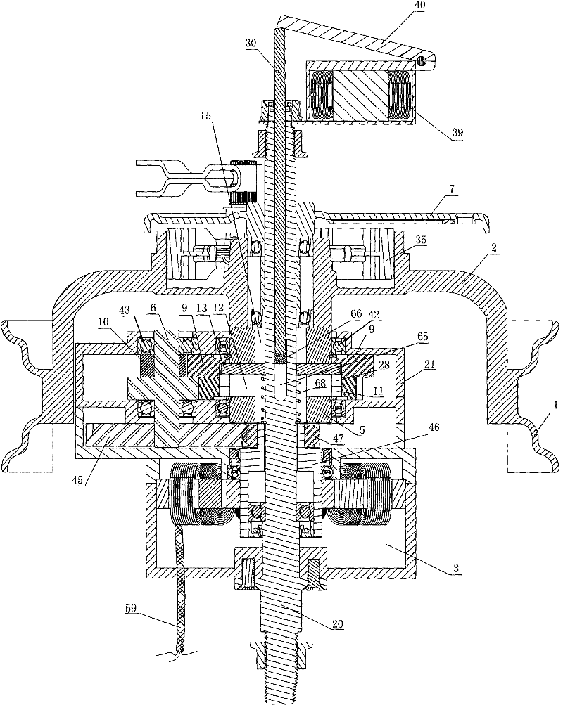
[0042] Such as image 3 Shown in, it is different from embodiment 1,2 except that: stepper motor 31 or lever bracket 41 are not established on the fulcrum 20, and electromagnetic suction 39 is established.
[0043] In the initial state, such as image 3 , Figure 5 As shown in , the stopper 13, the adjustment rod 30 and the suction plate 40 are pushed outward under the action of the elastic force of the return spring 68 on the support shaft 20, at this time the stopper 13 leaves the annular neutral gear 28 and blocks the slave of the low gear. In the driven gear inner groove 11, the stopper 13 is combined with the driven gear 9 hollow output shaft 5 of the low gear to rotate. The driven gear 9 of the low gear drives the hollow output shaft 5 to rotate, and the hollow output shaft 5 connects the end face 2 and the hub ring 1 to rotate around the fulcrum 20, which is now the first gear.
[0044] When the electromagnetic suction 39 is energized, the electromagnetic suction 39 ...
PUM
 Abstract
Description
Claims
Application Information
 - R&D
- Intellectual Property
- Life Sciences
- Materials
- Tech Scout
- Unparalleled Data Quality
- Higher Quality Content
- 60% Fewer Hallucinations
Browse by: Latest US Patents, China's latest patents, Technical Efficacy Thesaurus, Application Domain, Technology Topic, Popular Technical Reports.
© 2025 PatSnap. All rights reserved.Legal|Privacy policy|Modern Slavery Act Transparency Statement|Sitemap|About US| Contact US: help@patsnap.com


