
Integrated condenser

A condenser, all-in-one technology, used in evaporators/condensers, refrigerators, refrigeration components, etc., can solve problems such as large total volume and achieve the effect of small footprint

Inactive Publication Date: 2012-05-02
SUZHOU JIAYAN ENERGY EQUIP
View PDF8 Cites 4 Cited by
  • Summary
  • Abstract
  • Description
  • Claims
  • Application Information

AI Technical Summary

Problems solved by technology

[0002] At present, with the rapid development of the HVAC industry, heat pump units have been widely used in various heating and cooling equipment, and as one of the main components of heat pump units, the optimal design of the condenser has also become a hot topic. It is to dissipate the heat stored in the high-temperature gaseous condensing agent in its own condensation pipe to the surrounding low-temperature environment, so that the gaseous condensing agent is liquefied into a liquid condensing agent, and the current condenser (such as the external unit of the air conditioner) is mainly composed of heat-dissipating copper The copper pipe is connected with the heat sink as a whole, and the fan is independent, blowing air on the heat dissipation copper pipe and the heat sink, so that the cold air will take away the heat of the gaseous condensate in the heat dissipation pipe and make it liquefied , In addition, the structure of the entire condenser should also consider the optimal design of the support and ventilation, so its total volume is relatively large

Method used


Image

  • Integrated condenser
  • Integrated condenser

Examples


Embodiment Construction

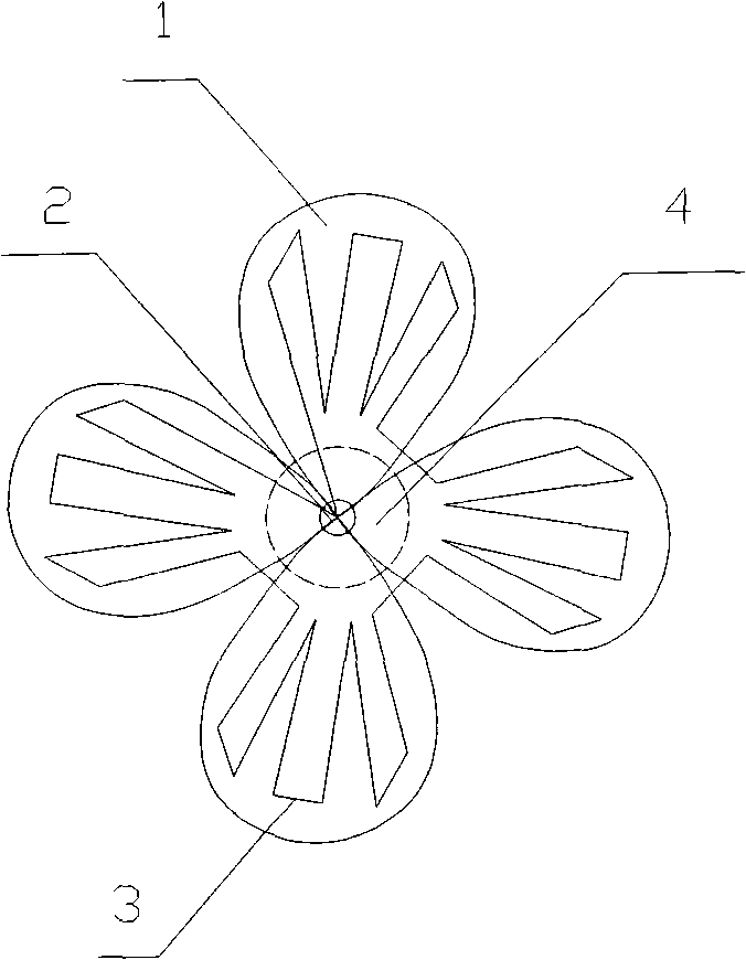
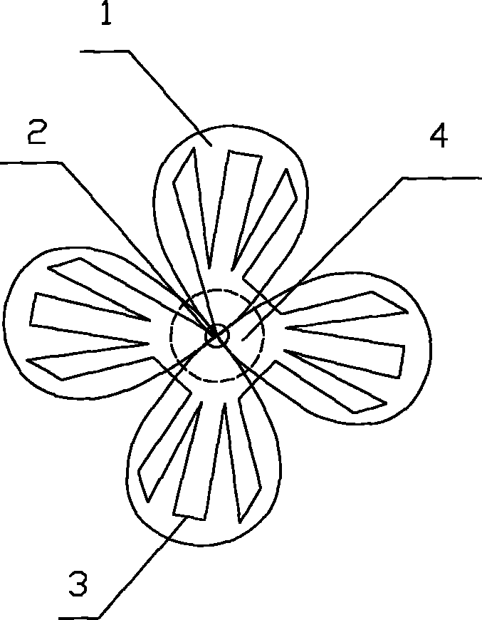
[0009] In the specific embodiment shown in the accompanying drawings, the integrated condenser consists of a fan blade (1), a rotating shaft and a bracket

[0010] (2), consisting of heat dissipation copper tube (3) and motor (4), among which the fan blades (1) have 3-4 pieces in total, made of aluminum sheet to make the fan blade shape of a common fan, and the heat dissipation copper tube (3) is clamped in the middle The part of the heat dissipation copper pipe (3) is divided into 3-4 parts, and each part is clamped on each fan blade (1) in a repeated circuitous curve. , each part of the cooling copper tube (3) is seamlessly connected in series, and its overall outlet and inlet are led out from the center of the rotating shaft of the fan blade to the rear of the fan blade, and the motor (4) directly drives each fan blade (1) to rotate. With the operation of the heat pump unit, the motor (4) drives the fan blades (1) to rotate, and the cold air directly passes over the surface...


PUM


Abstract

The invention relates to an integrated condenser, which is used for condensing a high-temperature gas condensing agent in a heat pump unit. The integrated condenser consists of fan blades, a rotating shaft and a bracket, radiation copper pipes and a motor, wherein 3-4 fan blades are arranged; the fan blades are manufactured in the shape of the fan blades of an ordinary fan by using aluminum sheets; parts used for clamping the radiation copper pipes in the middle of the fan blades are hollow; each radiation copper pipe is divided into 3-4 sections; each section of the radiation copper pipes is clamped on each fan blade circuitously, shown as pictures in the specification: each clamping seam is welded by a welding gun to be sealed; the sections of the radiation copper pipes are serially connected; an outlet and an inlet of the whole body are led out to the back of the fan blades from the center of the rotating shaft of the fan blades; and the motor directly drives the fan blades to rotate. When the integrated condenser works, the fan blades are driven to rotate by the motor with the operation of the heat pump unit so that cooling air directly blows through the surfaces of the fan blades. Therefore, heat on the radiation copper pipes and the aluminum fan blades is brought away rapidly so that the temperature of the high-temperature gas condensing agent in the radiation copper pipes is rapidly reduced until the gas condensing agent is liquefied. The condenser can be used for effectively condensing the high-temperature gas condensing agent, and the radiation copper pipes, radiation sheets and a fan are integrated into the whole body with a small occupy space.

Description

Technical field [0001] The invention relates to an integrated condenser capable of condensing in a heat pump unit, in particular to an integrated condenser which can integrate a fan and a heat dissipation copper pipe and occupies less space. Background technique [0002] At present, with the rapid development of the HVAC industry, heat pump units have been widely used in various heating and cooling equipment, and as one of the main components of heat pump units, the optimal design of the condenser has also become a hot topic. It is to dissipate the heat stored in the high-temperature gaseous condensing agent in its own condensation pipe to the surrounding low-temperature environment, so that the gaseous condensing agent is liquefied into a liquid condensing agent, and the current condenser (such as the external unit of the air conditioner) is mainly composed of heat-dissipating copper The copper pipe is connected with the heat sink as a whole, and the fan is independent, blo...

Claims


Application Information

Patent Timeline
IPC IPC(8): F25B39/04
Inventor 葛波
Owner SUZHOU JIAYAN ENERGY EQUIP
Learn More