
Drill rod assembling and disassembling mechanical arm of myriameter well drill

A technology for manipulators and drilling machines, applied in drill pipes, drilling equipment, drill pipes, etc., can solve the problems of high cost, large volume, poor structural flexibility, etc., and achieve convenient transportation and station transfer, flexible and accurate movement, and simple structure. Effect

Inactive Publication Date: 2013-07-10
JILIN UNIV
View PDF2 Cites 0 Cited by
  • Summary
  • Abstract
  • Description
  • Claims
  • Application Information

AI Technical Summary

Problems solved by technology

[0002] The utility model patent with the patent number ZL200820123890.5 discloses "a power catwalk" and the utility model patent with the patent number ZL200920033104.7 discloses a "wire rope pull-up drilling rig power catwalk". The technology of the above two patents The method of transporting the drill pipes in the scheme is basically the same, and all have the following disadvantages: 1. The structure is complex and the cost is high; 2. The drill pipe can only be sent to the well platform obliquely; 3. It is bulky and inconvenient for transportation and transfer; 4. The structure Poor flexibility, difficult to debug

Method used


Image

  • Drill rod assembling and disassembling mechanical arm of myriameter well drill
  • Drill rod assembling and disassembling mechanical arm of myriameter well drill
  • Drill rod assembling and disassembling mechanical arm of myriameter well drill

Examples


Embodiment Construction

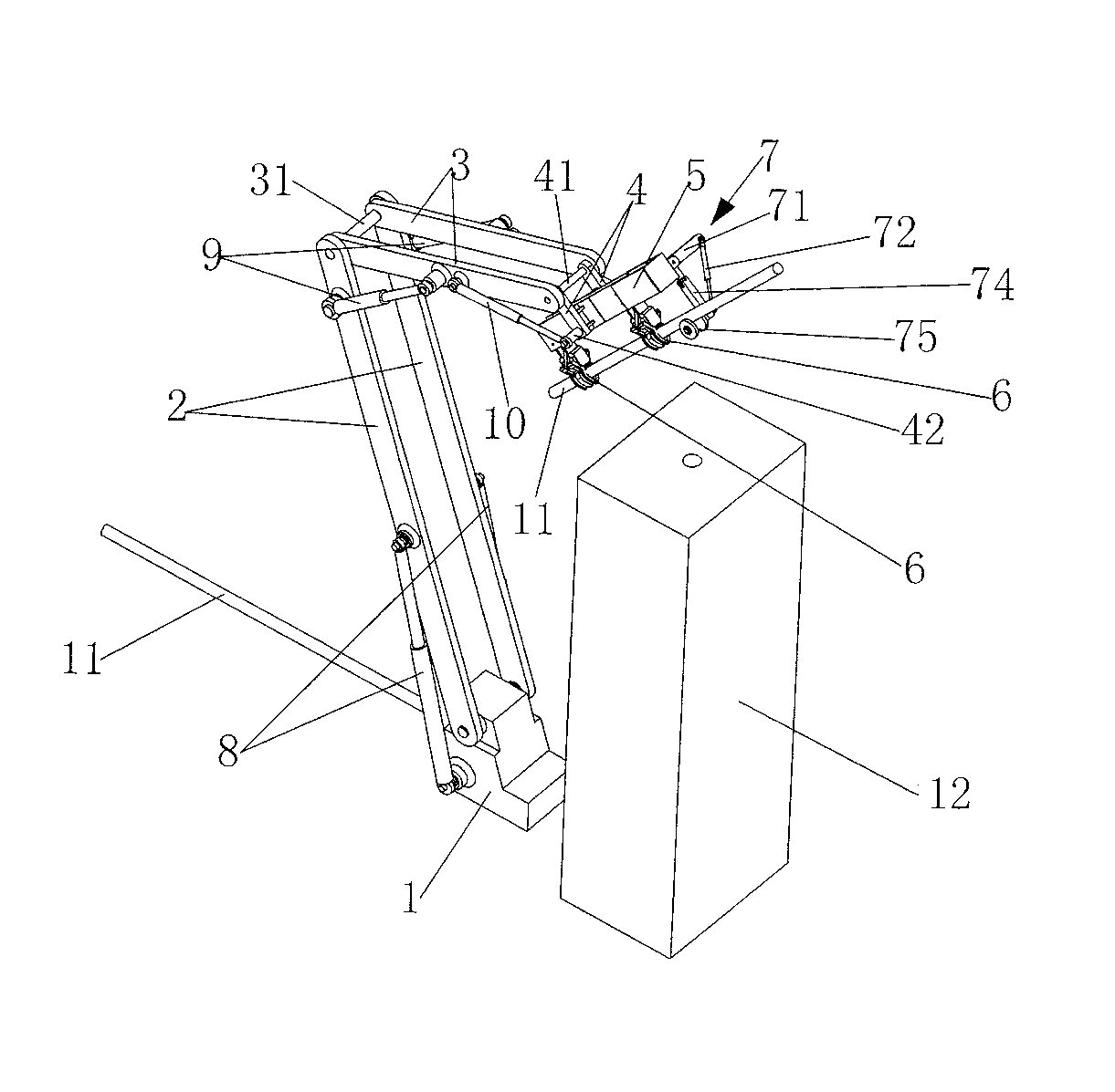
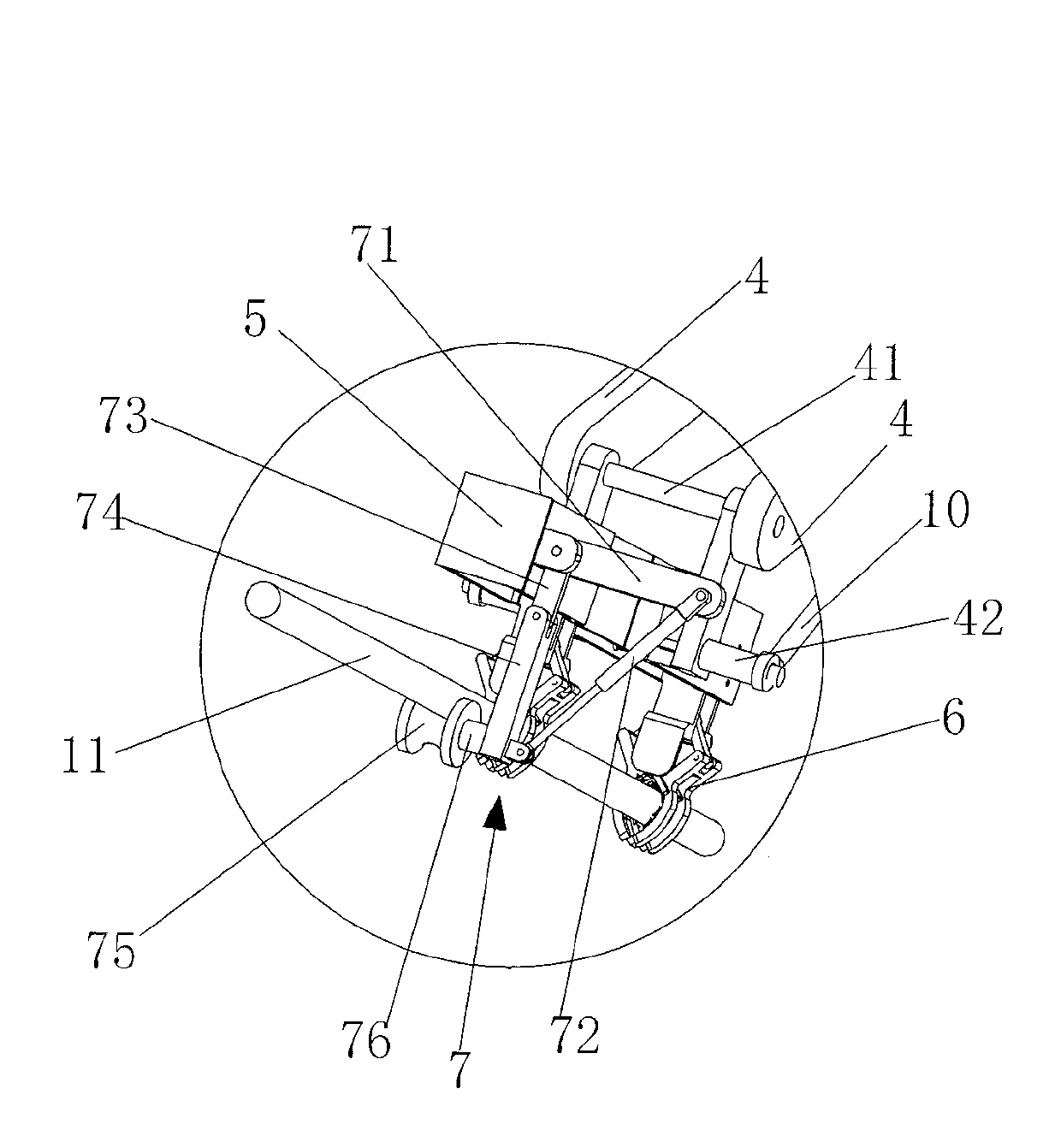
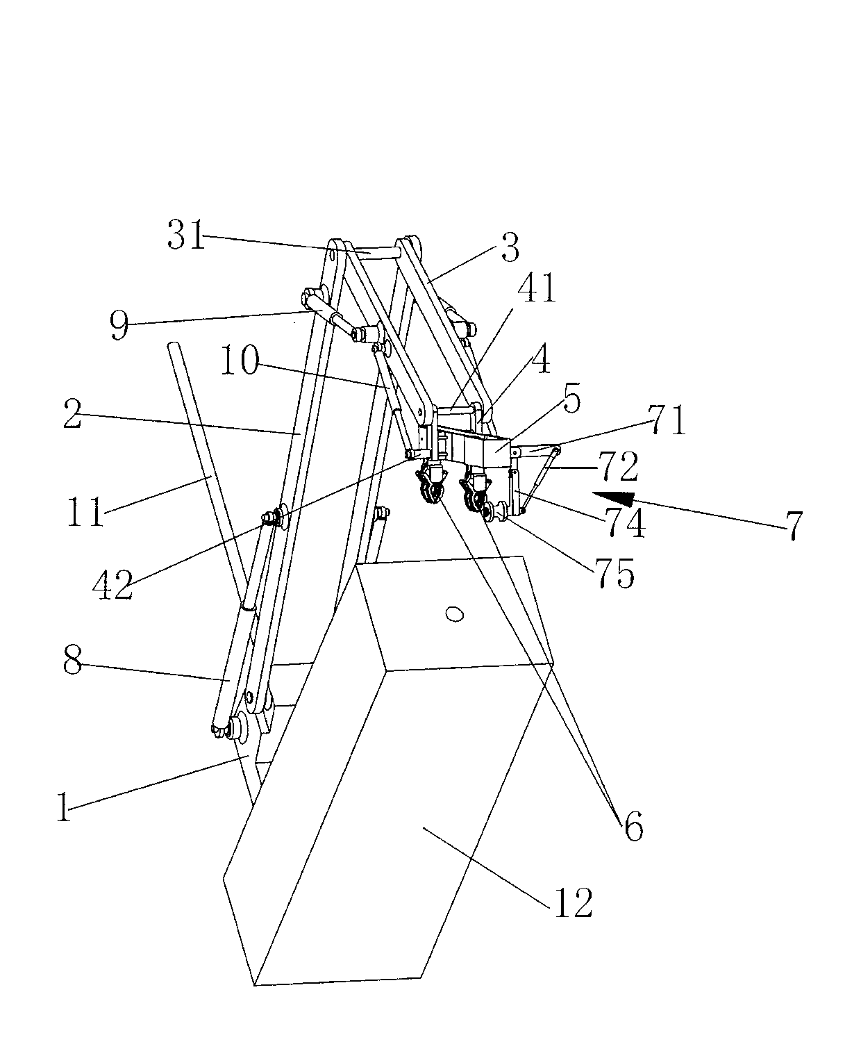
[0017] see figure 1 , figure 2 , image 3 , Figure 4 , Figure 5 and Figure 6 Shown, the present invention is made of base 1, two first connecting rods 2, two second connecting rods 3, two third connecting rods 4, suspension beam 5, two mechanical grippers 6, pipe supporting mechanism 7, two One first hydraulic cylinder 8, two second hydraulic cylinders 9 and two third hydraulic cylinders 10, the lower ends of the two first connecting rods 2 are hinged on the left and right sides of the base 1, the lower ends of the two second connecting rods 3 The shafts 31 are hinged on the inner sides of the upper ends of the two first connecting rods 2, the lower ends of the two third connecting rods 4 are hinged on the inner sides of the upper ends of the two second connecting rods 3 by shafts 41, and the upper ends of the two third connecting rods 4 The inner side fixes the suspension beam 5 along the direction, and the bottom of the suspension beam 5 is provided with two mechani...


PUM


Abstract

The invention discloses a drill rod assembling and disassembling mechanical arm of a myriameter well drill, which is composed of a base, four sections of connecting rods connected in hinged mode, a suspension girder, two mechanical catching hands, a pipe holder mechanism, three groups of hydraulic cylinders. The three groups of hydraulic cylinders are respectively hinged between the base and the connecting rods and between the connecting rods. The suspension girder is fixed between two connecting rods of a fourth section, the two mechanical catching hands are arranged at the bottom of the suspension girder and arranged in a front and back mode, and the pipe holder mechanism is arranged on the outer side of the front end of the suspension girder. The pipe holder mechanism is composed of a fixed cantilever, a hydraulic cylinder, a vertical arm, a movable arm and a supporting wheel. After the hydraulic cylinder of the pipe holder mechanism is contracted, the supporting wheel is driven tooverturn outwards to the outer side; and after the hydraulic cylinder extends, the supporting wheel is driven to overturn inwards to the position below the suspension girder and can be supported on the bottom surface of a drill rod. The drill rod assembling and disassembling mechanical arm not only enables the drill rod to be conveyed to a well platform in a perpendicular-to-the-ground mode, but also enables the drill rod to be conveyed to the well platform in an inclined mode, and can carry out reverse-direction operation and dismantle the drill rod.

Description

technical field [0001] The invention relates to oil drilling equipment, in particular to a manipulator for loading and unloading drill rods of a 10,000-meter drilling rig. Background technique [0002] The utility model patent with the patent number ZL200820123890.5 discloses "a power catwalk" and the utility model patent with the patent number ZL200920033104.7 discloses a "wire rope pull-up drilling rig power catwalk". The technology of the above two patents The method of transporting the drill pipes in the scheme is basically the same, and all have the following disadvantages: 1. The structure is complex and the cost is high; 2. The drill pipe can only be sent to the well platform obliquely; 3. It is bulky and inconvenient for transportation and transfer; 4. The structure Poor flexibility and difficult to debug. Contents of the invention [0003] The object of the present invention is to provide a 10,000-meter drilling machine drill pipe loading and unloading manipulato...

Claims


Application Information

Patent Timeline
Patent Type & Authority Patents(China)
IPC IPC(8): E21B19/18E21B19/14
Inventor 王继新宋嗣新孙友宏王清岩高科
Owner JILIN UNIV
Learn More