
Pressure quenching process and equipment for diaphragm spring

A diaphragm spring and equipment technology, applied in the field of diaphragm spring press quenching process and equipment, can solve the problems of limited fatigue life of diaphragm spring, limited hardness of diaphragm spring, long heating cycle, etc., achieving obvious energy saving effect and reducing brittleness , the effect of prolonging life

Inactive Publication Date: 2012-05-02
CHINA & CANTON CLUTCH
View PDF3 Cites 6 Cited by
  • Summary
  • Abstract
  • Description
  • Claims
  • Application Information

AI Technical Summary

Problems solved by technology

[0002] Diaphragm spring is one of the important parts of automobile diaphragm clutch, which plays the role of generating pressure on the pressure plate, cutting off power, overload protection, etc. The performance and life of the diaphragm spring determine the service life of various indicators of the clutch , the last process of the diaphragm spring in the manufacturing process is heat treatment. At present, the existing technology basically adopts the heating method of electric resistance furnace, so the heating cycle is long. The important thing is, in order to avoid the easy heating of the diaphragm spring in the air Oxidation or decarburization requires atmospheric oxidation protection and consumes more energy for a long time. At the same time, the hardness of the diaphragm spring manufactured by this technology is limited, and the fatigue life of the diaphragm spring is relatively limited. there are certain shortcomings

Method used


Image

  • Pressure quenching process and equipment for diaphragm spring
  • Pressure quenching process and equipment for diaphragm spring

Examples


Embodiment Construction

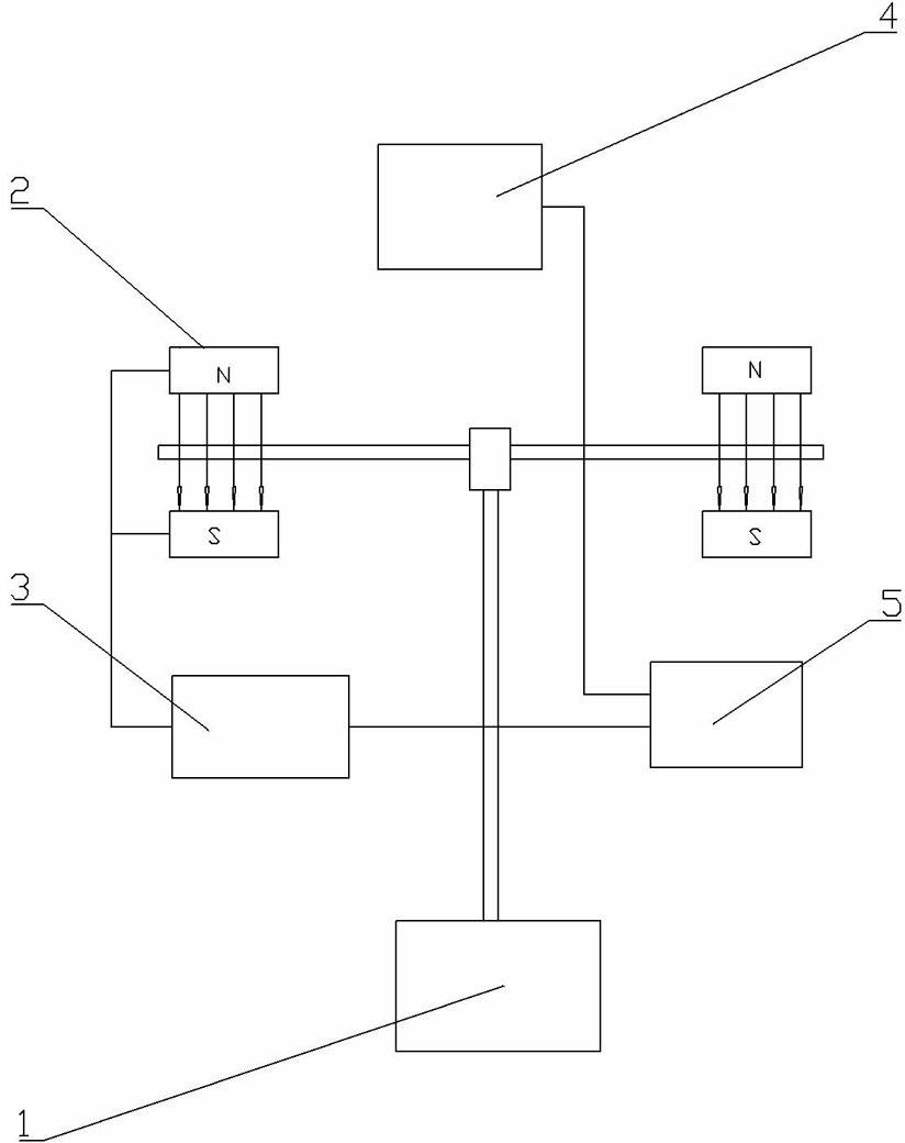
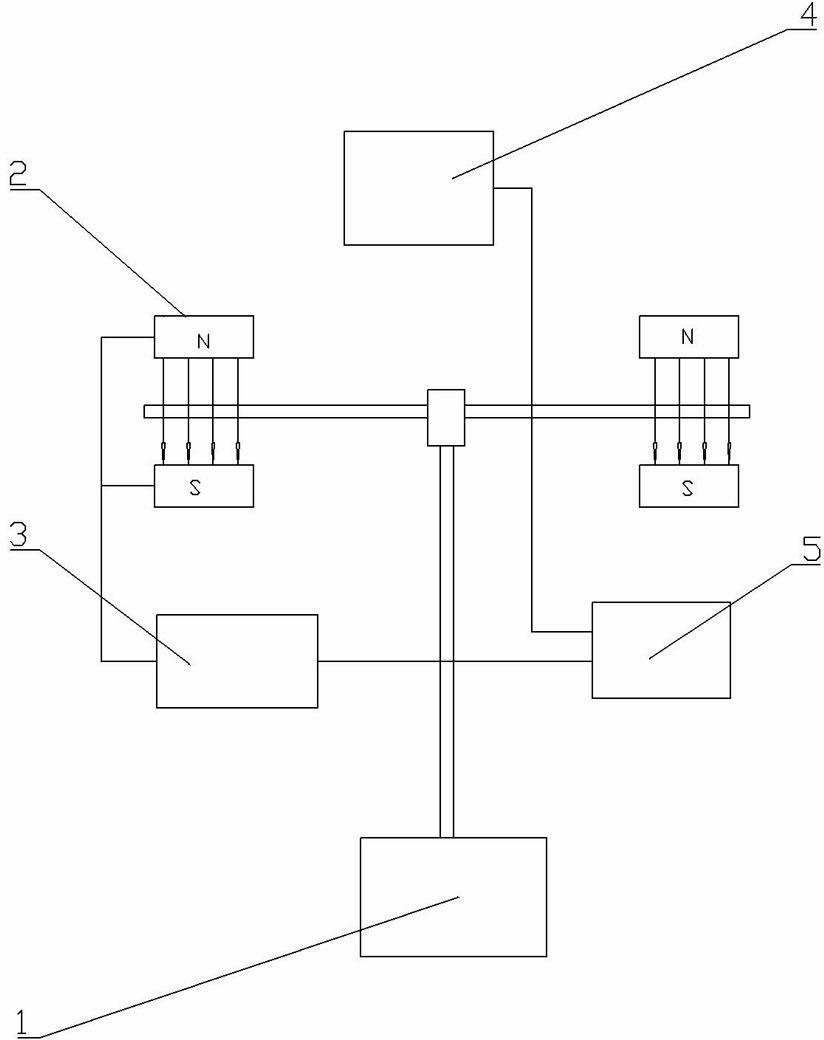
[0012] like figure 1 As shown, the key to realizing the press quenching method of the present invention lies in the press quenching equipment, which includes a rotating device 1, an induction coil 2, a high frequency power generating device 3, a temperature sensor 4, and an intelligent control device 5. In order to carry out intelligent control and comprehensive management, the rotating device 1, the high-frequency power generating device 3, and the temperature sensor 4 are all electrically connected to the intelligent control device 5, and the rotating device 1 includes a motor and is arranged on a motor rotating Clamping device on the shaft for clamping the diaphragm spring.

[0013] The working principle of the present invention is: after fixing the diaphragm spring on the rotating device 1, the intelligent control device 5 controls the rotation of the rotating device 1, and at the same time, controls the high-frequency power generating device 3 to provide 200 -250KH Z Th...


PUM


Abstract

The invention discloses a pressure quenching process and equipment for a diaphragm spring, aiming to provide a pressure quenching process and equipment which are short in heating period and good in energy-saving effect, and can improve the hardness and prolong the fatigue life. The pressure quenching equipment comprises a rotating device, an induction coil and a high-frequency current generator, wherein the high-frequency current generator is electrically connected with the induction coil; and the diaphragm spring is arranged on the rotating device for rotating and cutting a high-frequency magnetic field generated by the induction coil to generate an induction current. According to the invention, a high-frequency quenching mode is adopted to rapidly form and cool the diaphragm spring so as to achieve the hardness and metallographic structure required by heat treatment, thus reducing the heating period, having short time without oxidation, being free from atmosphere oxidation protection, and having an obvious energy-saving effect. Simultaneously, the high-frequency quenching mode can lead the metallographic structure of a material to be switched in a short period of time and form fine invisible martensite on the surface of the material, thus improving the surface hardness of the material and prolonging the service life of the diaphragm spring.

Description

technical field [0001] The invention relates to a diaphragm spring press quenching process and equipment. Background technique [0002] Diaphragm spring is one of the important parts of automobile diaphragm clutch, which plays the role of generating pressure on the pressure plate, cutting off power, overload protection, etc. The performance and life of the diaphragm spring determine the service life of various indicators of the clutch , the last process of the diaphragm spring in the manufacturing process is heat treatment. At present, the existing technology basically adopts the heating method of electric resistance furnace, so the heating cycle is long. The important thing is, in order to avoid the easy heating of the diaphragm spring in the air Oxidation or decarburization requires atmospheric oxidation protection and consumes more energy for a long time. At the same time, the hardness of the diaphragm spring manufactured by this technology is limited, and the fatigue lif...

Claims


Application Information

Patent Timeline
Patent Type & Authority Applications(China)
IPC IPC(8): C21D9/02C21D1/673
Inventor 伍金水
Owner CHINA & CANTON CLUTCH
Learn More