Combined filling station

A combined and filling technology, used in packaging, bottle filling, liquid bottling, etc., can solve problems such as unfavorable time and cost, and achieve the effect of simplifying product conversion

Active Publication Date: 2016-03-16
SYNTEGON TECHNOLOGY GMBH
View PDF6 Cites 0 Cited by
  • Summary
  • Abstract
  • Description
  • Claims
  • Application Information

AI Technical Summary

Problems solved by technology

[0003] The spatial separation of the conveying systems used is particularly disadvantageous during filling processes under isolator conditions or requires a considerable amount of time and cost when retrofitting the filling machine due to a changeover of the product to be filled

Method used


Image

  • Combined filling station
  • Combined filling station
  • Combined filling station

Examples


Embodiment Construction

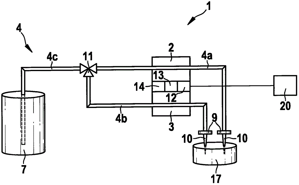
[0021] Refer below figure 1 The combined filling station according to the first preferred embodiment of the present invention is described in detail.

[0022] as by figure 1 The schematic diagram of the embodiment of the combined filling station 1 according to the invention can be seen, the combined filling station comprises a first conveying device 2 and a second conveying device 3, which pump through a pipeline device 4 Or take out the liquid that is stored in a storage container 7 . Here, the delivery devices 2 , 3 are of different types and can be hose pumps or rotary slide valve vacuum pumps or rotary piston pumps or rolling diaphragm pumps or time-pressure-filling systems. The line arrangement 4 comprises a distribution section 4c and a changeover / insertion device 11, on which a subsequent first line section 4a is tapped off from the distribution section 4c, the first line section It extends through the first conveying device 2 as far as the discharge point 9 . A sub...


PUM


Abstract

The invention relates to a combined filling station for bottling fluids, comprising a plurality of delivery devices (2, 3) for delivering the fluids, wherein the delivery devices (2, 3) are arranged in the combined filling station, and to a tubing device (4) for feeding the fluid to the delivery devices (2, 3) and for distributing the fluid from the delivery devices (2, 3) to a dispensing position (9), wherein the combined filling station has at least two differently designed delivery devices (2, 3).

Description

technical field [0001] The invention relates to a combined filling station for filling liquids, which has a plurality of conveying devices arranged in the combined filling station, and to a combined filling station with such the isolator. Background technique [0002] For the filling, especially of pharmaceutical liquids, filling machines with spatially separated filling or conveying systems are currently used in order to achieve filling to the respective product via a respective conveying system optimized for the respective filled product. Product conversion. [0003] The spatial separation of the conveying systems used is particularly disadvantageous during filling processes under isolator conditions or requires considerable time and cost in retrofitting the filling machine due to a changeover of the product to be filled. Contents of the invention [0004] The combined filling station according to the invention with the features of claim 1 has the advantage over this t...

Claims


Application Information

Patent Timeline
Patent Type & Authority Patents(China)
IPC IPC(8): B65B3/00B67C3/20
CPCB67C3/20
Inventor M·布罗伊宁格K·乌尔赫尔K·亨泽
Owner SYNTEGON TECHNOLOGY GMBH
Why Eureka
Try Eureka