


Quick Research
Generate reliable direction feasibility study reports for your R&D in just a few steps.

Technical Q&A
Discover and master advanced knowledge NOW. Basics, ideas, possibilities, all at once.

Find Solutions
As an expert in R&D theories, this can generate solutions to your technical problems instantly.

Evaluate Feasibility
Analyze your overall solution with one click, know your potential R&D risks in advance.

Monitor Landscape
Get weekly tech updates, stay abreast of the latest tech innovations and key insights.
Methods for distributing reactive power compensation capacity and switching branch circuits of passive filter
A passive filter and filter branch technology, applied in reactive power compensation, reactive power adjustment/elimination/compensation, harmonic reduction devices, etc., can solve the problem of not being able to fully guarantee the quality of system power and affecting the safety of the system and equipment Economic operation, system protection malfunction and other issues
- Summary
- Abstract
- Description
- Claims
- Application Information
AI Technical Summary
Problems solved by technology
Method used
Image

Examples
Embodiment 1
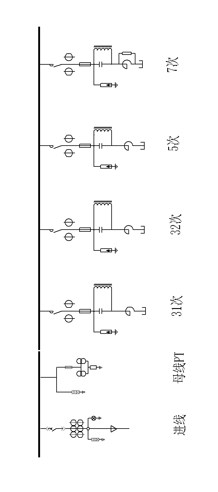
[0039] This embodiment is a method for distributing the reactive power compensation capacity of a passive filter. The passive filter designed according to the method has a plurality of filter branches, and the filter branches are composed of switching switches, capacitors, and resistors. , reactor and other components, such as figure 1 shown. The secondary control, measurement and protection loops of each filtering branch are connected with the controller.
[0040] The filter described in this embodiment is mainly used in a three-phase AC power supply system. The filter branch circuit adopts star connection, the neutral point is not grounded, and the switching switch, capacitor and reactor in the branch circuit are connected in series. A resistor and a capacitor are connected in parallel at both ends of the filter to form a high-pass or C-type filter branch, or no resistor or capacitor is connected in parallel to form a single-tuned filter branch. The number of filtering bra...
Embodiment 2
[0065] This embodiment is an improvement of the first embodiment, and is a refinement of the step of calculating the load rate of the filtering branch described in the first embodiment. The step of calculating the load rate of the filtering branch described in this embodiment includes the following sub-steps:
[0066] Calculate the load factor of the lowest harmonic filter branch : Take the calculated reactive power compensation amount and the total reactive power compensation amount when the mine monthly minimum load is taken If the reactive power compensation amount of the lowest harmonic filtering branch is relatively large, it can be split into two lowest harmonic filtering branches according to the ratio of reactive compensation amount 2:1;
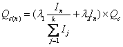
[0067] Calculation of load ratios to other filter branches , using the formula
[0068]
[0069] is the total number of harmonics, is the harmonic order, for The harmonic sequence number corresponding to the sub-harm...
Embodiment 3
[0072] This embodiment is a refinement of the above-mentioned embodiment, and is a refinement of the reactive power compensation amount of the n-time filter branch in the step of calculating the component parameters of each filter branch described in the above-mentioned embodiment. The reactive power compensation amount of the n-time filter branch in the step of calculating the component parameters of each filter branch described in the reactive compensation amount described in this embodiment Multiply by a factor of 1.04-1.13.
[0073] The reactance rate is the ratio of the reactance value of the series filter branch to the capacitive reactance value of the capacitor bank, which is used express. In the filter branch, the ratio of the branch loss compensation capacity to the branch capacitance compensation capacity is equal to the value of the reactance rate. The reactive power compensation capacity allocated by the filter branch refers to the effective compensation capaci...
PUM
 Abstract
Description
Claims
Application Information
 - R&D Engineer
- R&D Manager
- IP Professional
- Industry Leading Data Capabilities
- Powerful AI technology
- Patent DNA Extraction
Browse by: Latest US Patents, China's latest patents, Technical Efficacy Thesaurus, Application Domain, Technology Topic, Popular Technical Reports.
© 2024 PatSnap. All rights reserved.Legal|Privacy policy|Modern Slavery Act Transparency Statement|Sitemap|About US| Contact US: help@patsnap.com