Constant power valve

A technology of constant power and valve core, applied in the field of constant power valve, can solve the problems of low efficiency, high efficiency, large loss, etc., and achieve the effect of compact structure, reduced energy consumption, and improved efficiency

Active Publication Date: 2012-04-25
WUXI WEIFU PRECISION MACHINERY MFG
View PDF8 Cites 12 Cited by
  • Summary
  • Abstract
  • Description
  • Claims
  • Application Information

AI Technical Summary

Problems solved by technology

[0002] The traditional hydraulic system controls its flow and pressure through valves, but both pressure valves and flow valves will generate heat loss, resulting in high heat generation and low efficiency of the system. If it is a quantitative pump, this loss will be large
Existing constant pressure variable pumps can be used in systems that require pressure maintenance and pressure limiting, but the excess flow of variable pumps is still discharged back to the oil tank through the overflow valve, and the efficiency is not as high as that of constant power variable pumps

Method used


Image

  • Constant power valve
  • Constant power valve
  • Constant power valve

Examples


Embodiment Construction

[0014] The present invention will be further described below in conjunction with specific drawings and embodiments.

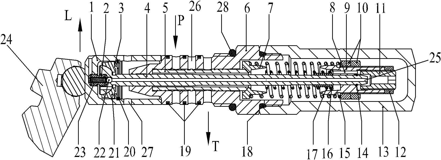
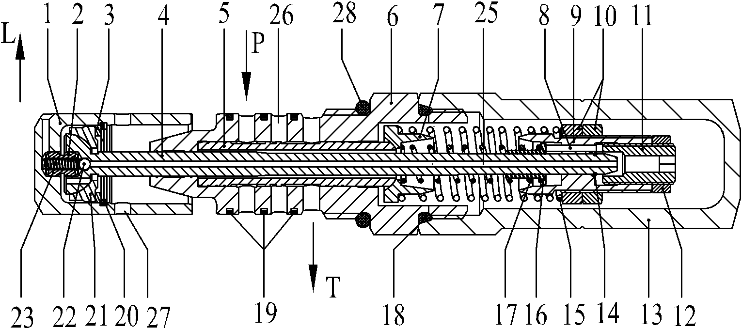
[0015] Such as Figure 1~Figure 3 Shown: the present invention includes adjusting piston 1, coupling 2, washer 3, piston rod 4, spool 5, piston guide sleeve 6, first spring seat 7, pressure pin 8, adjusting screw 9, adjusting screw nut 10, tight Fastening bolt 11, fastening bolt nut 12, protective cap 13, steel wire retaining ring for shaft 14, large spring 15, second spring seat 16, small spring 17, first O-ring 18, piston ring 19, screw stopper for hole Ring 20, spherical seat 21, steel ball 22, one-way valve spring 23, variable pump swash plate 24, hydraulic oil through hole 25, lateral middle hole 26, high-pressure oil inlet 27, second O-ring 28, load pressure Port P and oil discharge port T.

[0016] Such as figure 1 with figure 2 As shown: the constant power valve includes a piston guide sleeve 6, one end of the piston guide sleeve 6 is provided with...


PUM


Abstract

The invention relates to a constant power valve, which comprises a piston guide sleeve, wherein the outer wall of the piston guide sleeve is provided with a load pressure interface, a lateral middle hole and an oil discharging hole; a valve core is arranged in the piston guide sleeve; a piston rod is arranged in the valve core; a first spring seat is arranged in the end part of the piston guide sleeve which is correspondingly connected with a protective cap; the end part of the piston rod which correspondingly extends into the protective cap is provided with a reset adjusting spring; an adjusting piston is provided with a high-pressure oil inlet; the end part of the piston rod which correspondingly extends into the adjusting piston passes through a spherical seat and is correspondingly matched with the spherical seat; a hydraulic oil through hole which is distributed along the axis of the piston rod is formed in the piston rod, and can be communicated with a hydraulic oil outlet; the end part of the piston rod which correspondingly extends into the adjusting piston is provided with a shaft coupling; and a one-way valve spring is arranged in the shaft coupling, and is correspondingly matched with a steel ball for blocking the hydraulic oil through hole in the piston rod. The constant power valve has a compact structure, the efficiency of a hydraulic system is increased, and the energy consumption of the hydraulic system is lowered.

Description

technical field [0001] The invention relates to a valve body structure for a hydraulic pump, in particular to a constant power valve, which belongs to the technical field of hydraulic pumps. Background technique [0002] The traditional hydraulic system controls its flow and pressure through valves, but both pressure valves and flow valves will generate heat loss, resulting in high heat generation and low efficiency of the system. If it is a quantitative pump, this loss will be large. Existing constant pressure variable pumps can be used in systems that require pressure maintenance and pressure limiting, but the excess flow of the variable pump is still discharged back to the oil tank through the overflow valve, and the efficiency is not as high as that of the constant power variable pump. Contents of the invention [0003] The purpose of the present invention is to overcome the disadvantages of the prior art and provide a constant power valve with a compact structure, whi...

Claims


Application Information

Patent Timeline
IPC IPC(8): F04B53/10
Inventor 卢柏明
Owner WUXI WEIFU PRECISION MACHINERY MFG
Why Eureka
Try Eureka