
Air damper

A technology of air damping and air chamber, applied in the direction of gas shock absorber, shock absorber, shock absorber, etc., to achieve the effect of stable braking force

Inactive Publication Date: 2012-04-18
NIFCO INC
View PDF5 Cites 6 Cited by
  • Summary
  • Abstract
  • Description
  • Claims
  • Application Information

AI Technical Summary

Problems solved by technology

[0007] The present invention considers the above facts and solves the problem of stabilizing the braking force of the air damper

Method used


Image

  • Air damper
  • Air damper
  • Air damper

Examples


Embodiment Construction

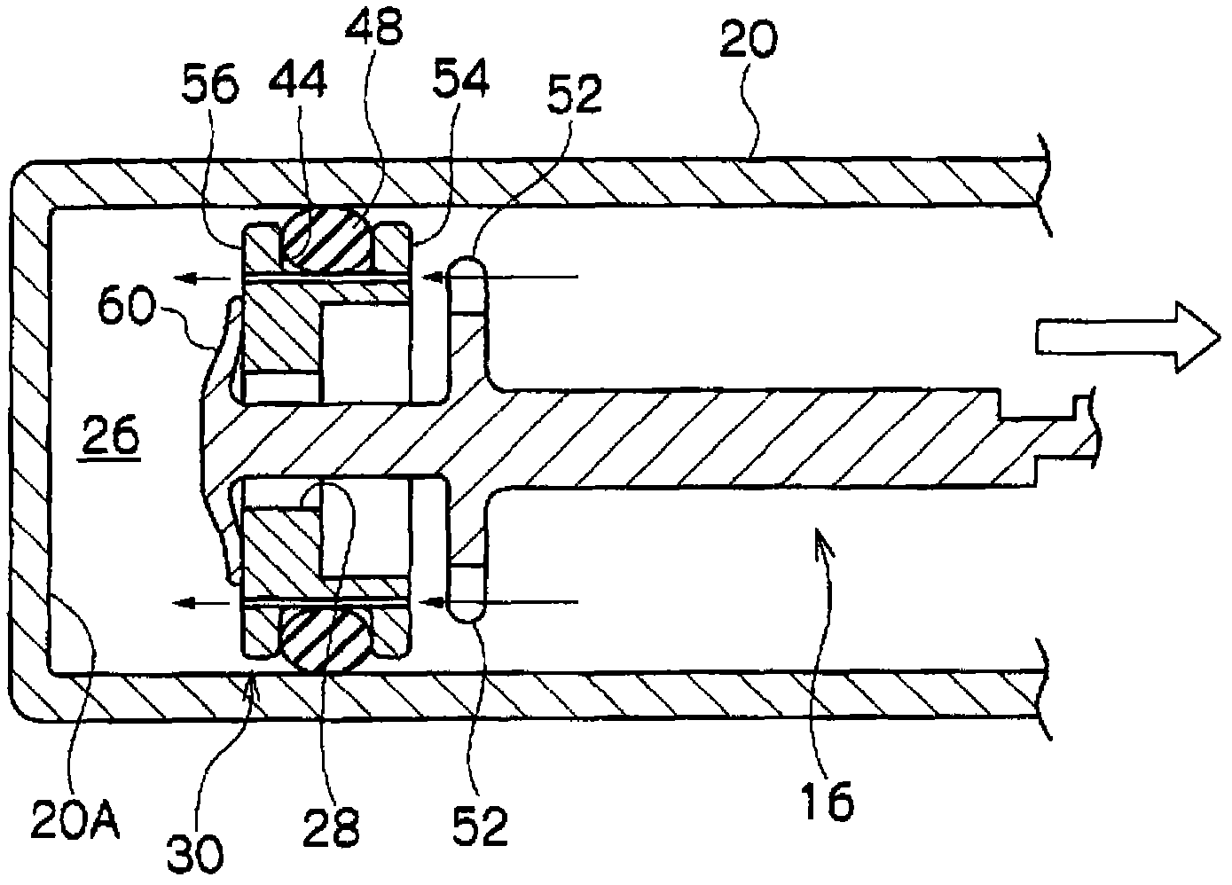
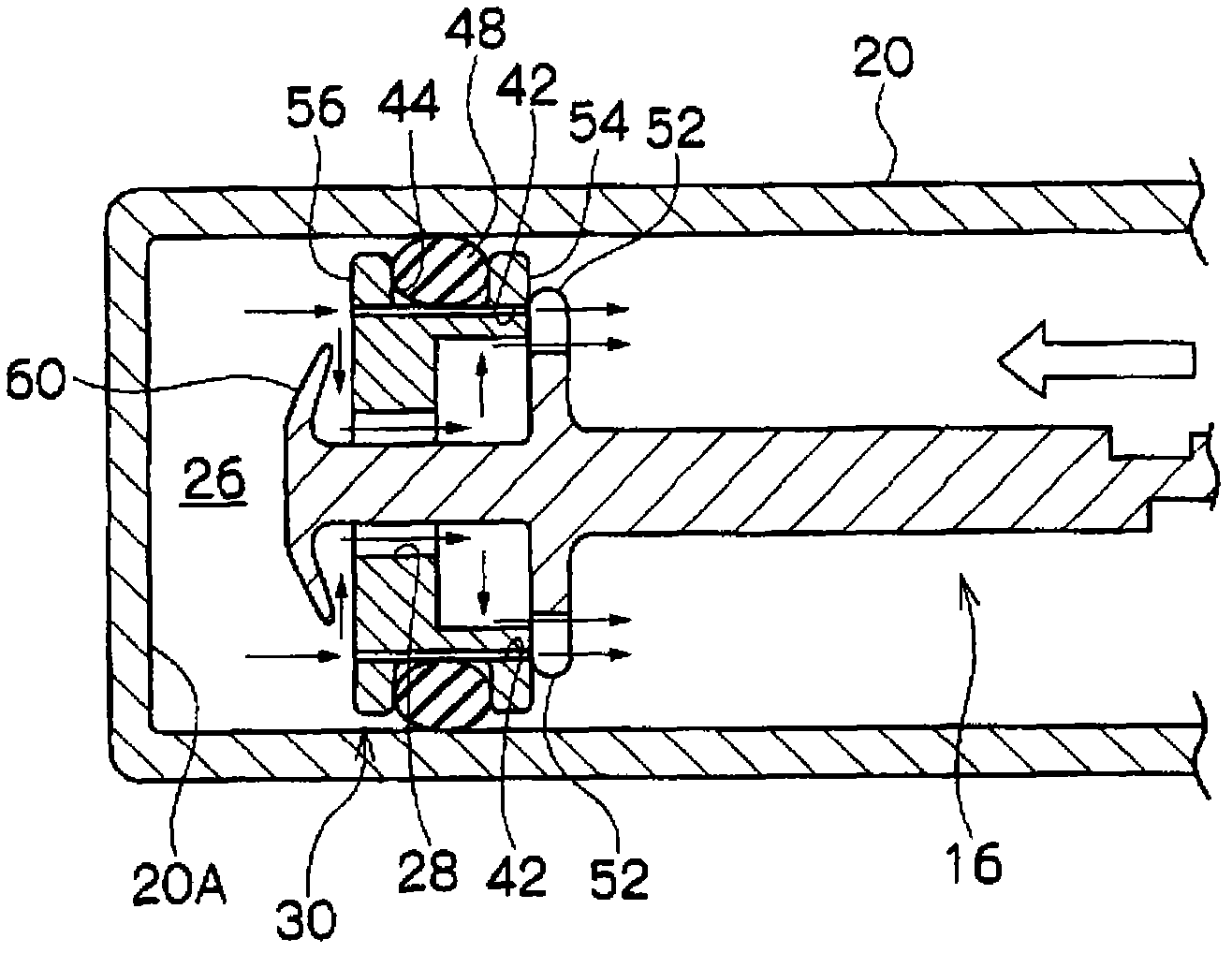
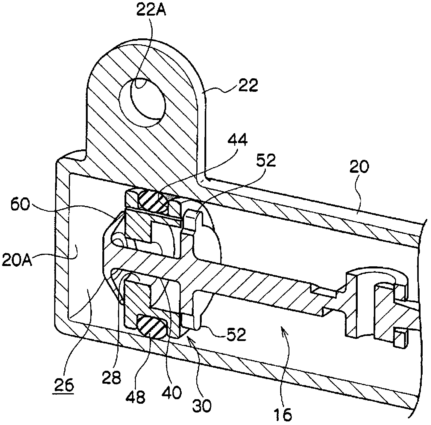
[0047] According to Figure 1~ Figure 7 A glove box using an example of the air damper according to the first embodiment of the present invention and the air damper will be described.

[0048] (the whole frame)

[0049] Such as Figure 7 As shown, a glove box 12 using an air damper 10 is provided in front of a passenger's seat in a vehicle interior. Furthermore, the glove box 12 includes a rotating shaft portion 14 that rotatably supports the glove box 12 on one end side. In addition, one end of the rod member 16 of the air damper 10 fixed to the vehicle body by a bracket (not shown) is locked to the other end side of the glove box 12 .

[0050] In addition, the glove box 12 is engaged with the vehicle body by an engaging mechanism not shown, and the engaging mechanism is released by gripping the grip portion 12A of the glove box 12 . Furthermore, the glove box 12 from which the engagement mechanism has been released rotates around the rotation shaft portion 14 by its own ...


PUM


Abstract

Provided is an air damper wherein the damping force can be stabilized. When a rod member (16) is extended outwards from a cylinder member (20), a suction plate member (60) comes into abutment with an opposite surface (56) of a piston member (30), closing an air passage (28), and the air passage which provides communication between an air chamber (26) and the outside is reduced to an orifice part (42). On the other hand, when the rod member (16) is pushed into the cylinder member (20), the suction plate member (60) moves away from the opposite surface (56) of the piston member (30), opening the air passage (28). As a result, the air passage (28) can be opened and closed in the intended fashion, and the damping force can be stabilized to a greater extent than a conventional structure in which an O-ring rolls under the friction force with the inner peripheral surface of the cylinder in order to open / close the air passage.

Description

technical field [0001] The present invention relates to an air damper which performs braking by causing the air in the air chamber in the cylinder to flow through a damping hole by relatively moving a piston in the cylinder. Background technique [0002] The air damper described in Patent Document 1 (JP-A-8-105481) is provided with a piston movable in a cylinder. Moreover, an orifice is formed on the piston so that the air in the air chamber in the cylinder and the outside can flow. [0003] In addition, an O-ring for sealing the piston and the inner peripheral surface of the cylinder is arranged in a recess formed on the outer peripheral surface of the piston. Moreover, an air passage is provided on the bottom surface of the recess, and when the piston is pulled out from the cylinder, the O-ring rolls in one direction in the recess by friction with the inner peripheral surface of the cylinder, thereby blocking the air passage, and when When the piston is pushed into the c...

Claims


Application Information

Patent Timeline
IPC IPC(8): F16F9/34F16F9/02F16F9/32
CPCF16F9/3415F16F9/0218F16F9/3221
Inventor 小川敦司
Owner NIFCO INC
Learn More