Current limiting protection circuit and direct current (DC)-DC converter integrated with current limiting protection circuit

A DC-DC, current-limiting protection technology, applied in the direction of output power conversion devices, electrical components, etc., to achieve the effect of preventing current tailing

Inactive Publication Date: 2014-02-26
UNIV OF ELECTRONICS SCI & TECH OF CHINA
View PDF2 Cites 0 Cited by
  • Summary
  • Abstract
  • Description
  • Claims
  • Application Information

AI Technical Summary

Problems solved by technology

[0005] The purpose of the present invention is to solve the existing problem of limiting the current peak value of the existing DC-DC converter, and propose a current limiting protection circuit

Method used


Image

  • Current limiting protection circuit and direct current (DC)-DC converter integrated with current limiting protection circuit
  • Current limiting protection circuit and direct current (DC)-DC converter integrated with current limiting protection circuit
  • Current limiting protection circuit and direct current (DC)-DC converter integrated with current limiting protection circuit

Examples


Embodiment Construction

[0017] The present invention will be further elaborated below in conjunction with the accompanying drawings and specific embodiments.

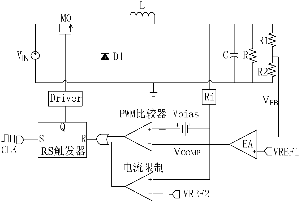
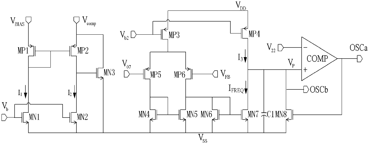
[0018] Aiming at the problems existing in the existing DC-DC converter to limit the peak value of the current, the present invention proposes a current-limiting protection circuit for the DC-DC converter, specifically as figure 2 As shown, it includes 6 PMOS transistors MP1, MP2, MP3, MP4, MP5, MP6 and 8 NMOS transistors MN1, MN2, MN3, MN4, MN5, MN6, MN7, MN8, capacitor C1 and comparator COMP. Wherein, the gates of PMOS transistors MP1 and MP2 are connected to the drain of MP1, the drains are respectively connected to the drains of MN1 and MN2, and the source of MP1 is connected to the external first reference voltage V BIAS , the source of MP2 is used as the voltage clamping output terminal of the current limiting protection circuit; the gates of NMOS transistors MN1 and MN2 are connected to the first external bias voltage V b1 , the gate o...


PUM


Abstract

The invention discloses a current limiting protection circuit and a direct current (DC)-DC converter integrated with the current limiting protection circuit. By the current limiting protection circuit, the DC-DC converter can control the output voltage of an error amplifier not to exceed a preset voltage value under a slight overload condition, so that a pulse width modulation (PWM) comparator can normally control the on / off of a control tube and further limit a peak value of inductance current; and under a severe overload or output short circuit condition, adverse impact caused by a transmission delay can be weakened by prolonging output square wave and slope compensation saw tooth wave cycles of an oscillator, thereby effectively preventing large current tails and protecting the converter from damage in any fault state. Moreover, the output frequency of the current limiting protection circuit is linearly changed, the phenomenon of state locking can be avoided in a starting process, and the converter can work normally.

Description

technical field [0001] The invention belongs to the technical field of integrated circuits, and in particular relates to the design of a current-limiting protection circuit for a DC-DC converter. Background technique [0002] Switching power supply has the advantages of high efficiency, large output current, and small size, and has become an important circuit in power management chips. [0003] A typical existing BUCK regulator structure is as follows figure 1 As shown, the feedback network composed of adjustment tube M0, capacitor L, Zener diode D1, resistors R1, R2, error amplifier, PWM comparator, drive circuit Driver, RS flip-flop, current limiting circuit, current sampling circuit Ri and load Composed of resistor R and load capacitor C. Under normal circumstances, the clock signal CLK will control M0 to turn on at the beginning of a cycle, and the current of the inductor L starts to increase. When the sampling voltage of the current sampling circuit exceeds the output...

Claims


Application Information

Patent Timeline
Patent Type & Authority Patents(China)
IPC IPC(8): H02M1/32
Inventor 周泽坤李涅王慧芳石跃明鑫张波
Owner UNIV OF ELECTRONICS SCI & TECH OF CHINA
Why Eureka
Try Eureka