
Mobile wireless monitoring and alarming fence system

A wireless monitoring and mobile technology, used in alarms, burglar alarms, instruments, etc., can solve the problems of cumbersome construction, large standby current, low reliability, etc. strong effect

Active Publication Date: 2012-04-18
WUHAN POWER TECH
View PDF6 Cites 14 Cited by
  • Summary
  • Abstract
  • Description
  • Claims
  • Application Information

AI Technical Summary

Problems solved by technology

[0011] ⑴High cost: The "one-time" cost of the electronic fence is higher than that of infrared radiation, and electronic cables need to be installed as part of the perimeter fence, which increases the construction cost and is cumbersome during implementation;
[0012] ⑵High risk: Electronic fences give people a sense of pressure. When they are accidentally touched, they may cause indirect injuries such as slipping and falling due to direct and strong electric shock. If children touch the fence by mistake, it may also have more serious consequences. ; Sometimes electric sparks will be generated, so it is not suitable to use in an environment with flammable gas, and a sufficient distance should be kept from the power line;
[0013] ⑶ Low reliability: the infrared fence will be interfered by other light sources and will fail;
[0014] ⑷Large power consumption: the infrared fence alarm system consumes a lot of power, and the usual standby current is large;
[0015] ⑸Small scope of application: The power supply of the electronic fence must use 220V mains power. If there is no mains power outdoors or in the field, this system cannot be used; the infrared fence alarm system consumes a lot of power and is not suitable for outdoor or field conditions.

Method used


Image

  • Mobile wireless monitoring and alarming fence system
  • Mobile wireless monitoring and alarming fence system
  • Mobile wireless monitoring and alarming fence system

Examples


Embodiment Construction

[0038] The preferred embodiments of the present invention will be described below with reference to the accompanying drawings. It should be understood that the preferred embodiments described herein are only used to illustrate and explain the present invention, but not to limit the present invention.

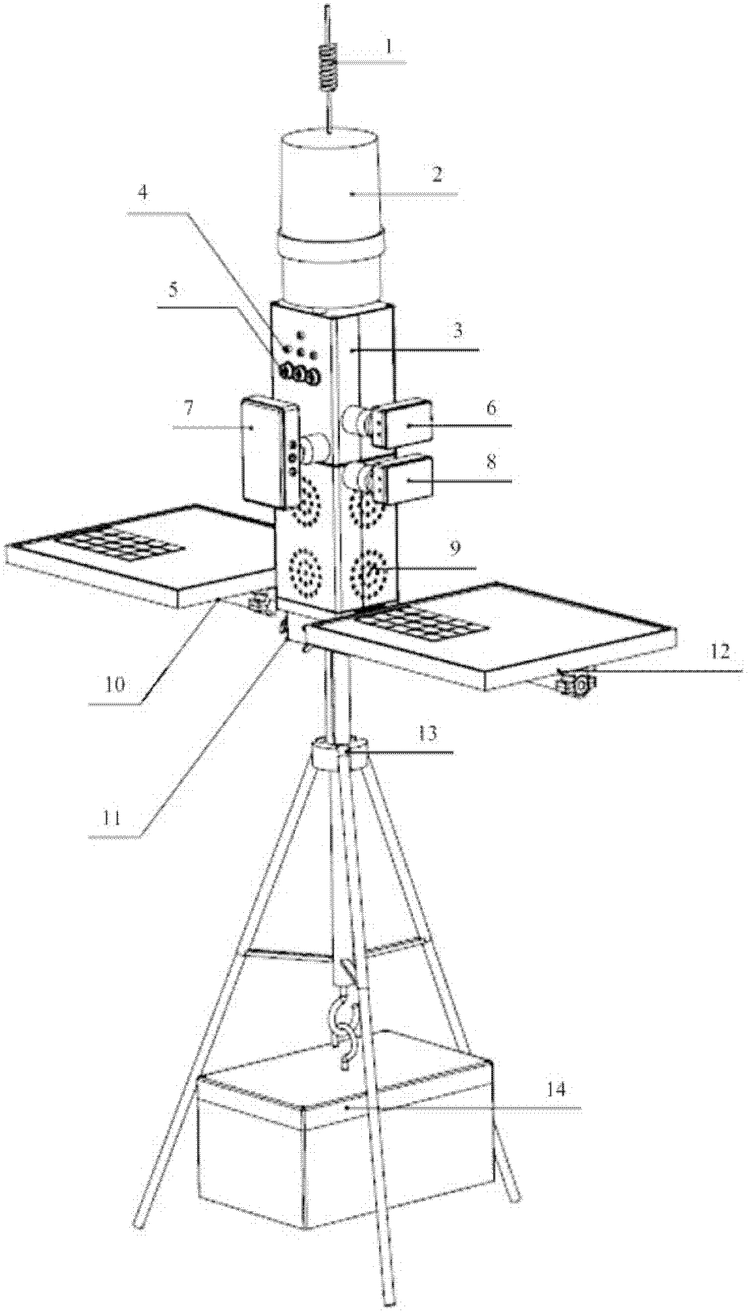
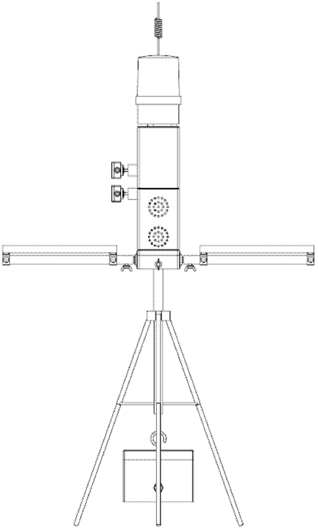
[0039] According to an embodiment of the present invention, a mobile wireless monitoring and alarming fence system is provided. like Figure 1-Figure 6 As shown, this embodiment includes a plurality of mobile wireless monitoring and alarm fences for on-site security and vertical intervals, and a monitoring center for remote monitoring of multiple mobile wireless monitoring and alarm fences; wherein: the monitoring center, and Wireless communication connection between multiple mobile wireless monitoring and alarm fences; between two adjacent mobile wireless monitoring and alarm fences, through signal transmission and signal reception, signal cross-fire connection is carried out. ...


PUM


Abstract

The invention discloses a mobile wireless monitoring and alarming fence system, which comprises multiple mobile wireless monitoring and alarming fences and a monitor center, wherein the multiple mobile wireless monitoring and alarming fences are used for field security protection and are vertically arranged at certain interval; the monitor center is used for remote monitoring of the multiple mobile wireless monitoring and alarming fences; the monitor center is in wireless communication connection with the multiple mobile wireless monitoring and alarming fences; and two adjacent mobile wireless monitoring and alarming fences are in signal correlation connection through signal sending and signal receiving. The mobile wireless monitoring and alarming fence system disclosed by the invention can overcome the defects of high cost, high risk, low reliability, large electric power consumption, small application range and the like in the prior art, and has the advantages of simpleness in installation, convenience for moving, no need for commercial power, low cost, good safety, high reliability, strong interference resistance, good stability, energy saving and environmental friendliness andlarge application range.

Description

technical field [0001] The invention relates to the field of security technology, in particular to a mobile wireless monitoring and alarming fence system. Background technique [0002] At present, as the most advanced perimeter anti-theft alarm system, the electronic fence consists of a high-voltage electronic pulse host and a front-end detection fence. The development of electronic fences comes from Europe and the United States, and modern electronic fences come from Australia. Electronic fences are divided into security electronic fences and animal husbandry electronic fences. Electronic fence has been widely used in China and has become the main product in the field of perimeter alarm. In 2008, the national standard for electric fence was promulgated, and its standard number is: GB / T7946-2008. [0003] In the above-mentioned electronic fence, the high-voltage electronic pulse host generates and receives high-voltage pulse signals, and can generate an alarm signal when t...

Claims


Application Information

Patent Timeline
IPC IPC(8): G08B13/181G08B25/10
CPCY02B60/50
Inventor 姚宏黄利群孙红郑敏东王张相
Owner WUHAN POWER TECH
Learn More