Light source module, surface area light-emitting unit, and surface area light-emitting device
A light source module and a surface-emitting technology, which is applied to semiconductor devices, light sources, and electric light sources of light-emitting elements, can solve the problems of uneven color and brightness of LED elements, simplify installation operations, and suppress uneven light emission and color unevenness. average and reduce manufacturing costs
- Summary
- Abstract
- Description
- Claims
- Application Information
AI Technical Summary
Problems solved by technology
Method used
Image
Examples
no. 1 approach
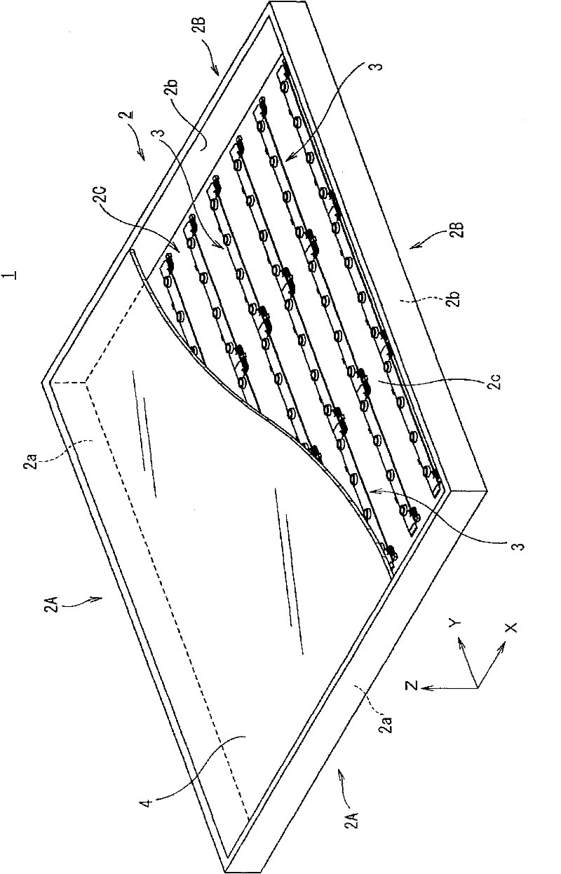
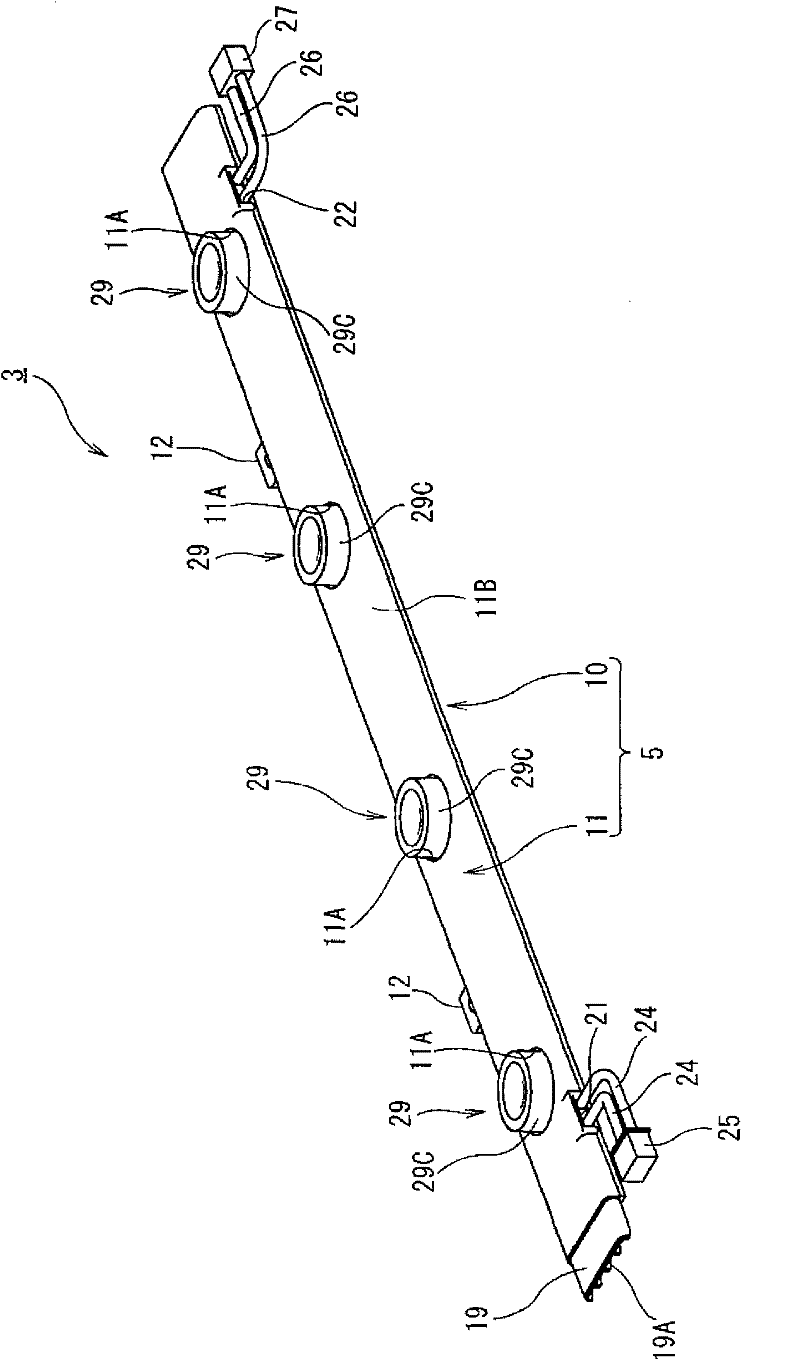
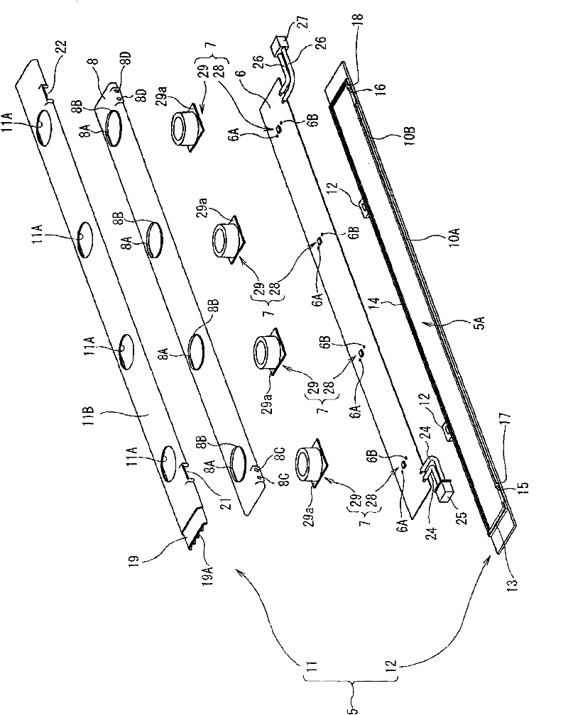
[0041] figure 1 It is a perspective view showing the whole of the surface light-emitting device including the surface light-emitting module according to the first embodiment of the present invention. figure 2 It is an assembly perspective view showing the whole of the surface emitting module according to the first embodiment of the present invention. image 3 It is an exploded perspective view showing the whole of the surface emitting module according to the first embodiment of the present invention. Figure 4 It is a perspective view showing the connected state of the surface light-emitting module according to the first embodiment of the present invention. Figure 5 It is a perspective view which shows the state which disconnected the connection of the surface emission module which concerns on 1st Embodiment of this invention. Image 6 It is a perspective view which shows the state which looked at the connection part of the surface light-emitting module which concerns on 1...
no. 2 Embodiment approach
[0093] Figure 14 It is an assembly perspective view showing the whole of the surface emitting module according to the second embodiment of the present invention. Figure 15 It is a cross-sectional view shown for explaining the light-emitting lamp of the surface light-emitting module according to the second embodiment of the present invention. Figure 15 (a) means Figure 14 A-A sectional view of, Figure 15 (b) means Figure 14 The B-B section view. Figure 16 It is a figure shown for explaining the light direction conversion part in the light emitting lamp of the surface light emitting module which concerns on the 2nd Embodiment of this invention. Figure 16 (a) represents a perspective view, Figure 16 (b) represents a top view, Figure 16 (c) shows a bottom view. Figure 17 It is a sectional view shown in order to explain the light direction conversion part in the light emitting lamp of the surface light emission module concerning 2nd Embodiment of this invention. ...
no. 3 Embodiment approach
[0103] Figure 18 It is a sectional view shown in order to explain the light direction conversion part in the light emitting lamp of the surface light emission module which concerns on 3rd Embodiment of this invention. The optical element for changing the direction of light of the third embodiment has an inclined light reflecting surface provided between the upper light reflecting surface 29B and the side light emitting surface 29C in the optical element 29 for light direction changing of the first embodiment. 29D.
[0104] The light emitted from the LED 28 and the light incident from the second light incident surface 29c on the bottom surface of the optical element 29 for light direction conversion are reflected by the light reflecting surface 29B on the top and almost emitted from the light emitting surface 29C on the side, but pass through the light on the light emitting surface 29C. A light reflection surface 29D approximately in the shape of a part of a cone is provided ...
PUM
 Abstract
Description
Claims
Application Information
 - Generate Ideas
- Intellectual Property
- Life Sciences
- Materials
- Tech Scout
- Unparalleled Data Quality
- Higher Quality Content
- 60% Fewer Hallucinations
Browse by: Latest US Patents, China's latest patents, Technical Efficacy Thesaurus, Application Domain, Technology Topic, Popular Technical Reports.
© 2025 PatSnap. All rights reserved.Legal|Privacy policy|Modern Slavery Act Transparency Statement|Sitemap|About US| Contact US: help@patsnap.com


