Long-slab-span steel beam cast-in-situ floor formwork system

A cast-in-situ floor slab and floor slab formwork technology, which is applied in the fields of formwork/formwork/work frame, on-site preparation of building components, construction, etc., can solve the problems of inconvenient installation and movement, heavy weight, large volume, etc. The effect of high utilization rate, reduced formwork cost and increased beam spacing

Active Publication Date: 2012-04-18
杨峰
View PDF9 Cites 10 Cited by
  • Summary
  • Abstract
  • Description
  • Claims
  • Application Information

AI Technical Summary

Problems solved by technology

However, due to the need to meet a certain rigidity, the entire "adjustable steel support" is large in size and heavy in weight, making it inconvenient to install and move

Method used


Image

  • Long-slab-span steel beam cast-in-situ floor formwork system
  • Long-slab-span steel beam cast-in-situ floor formwork system
  • Long-slab-span steel beam cast-in-situ floor formwork system

Examples


Embodiment Construction

[0026] The following describes in detail the embodiments of the present invention, examples of which are illustrated in the accompanying drawings, wherein like reference numerals refer to like elements throughout. The embodiments described below with reference to the accompanying drawings are used to explain the present invention, and the embodiments are exemplary and should not be construed as limiting the present invention.

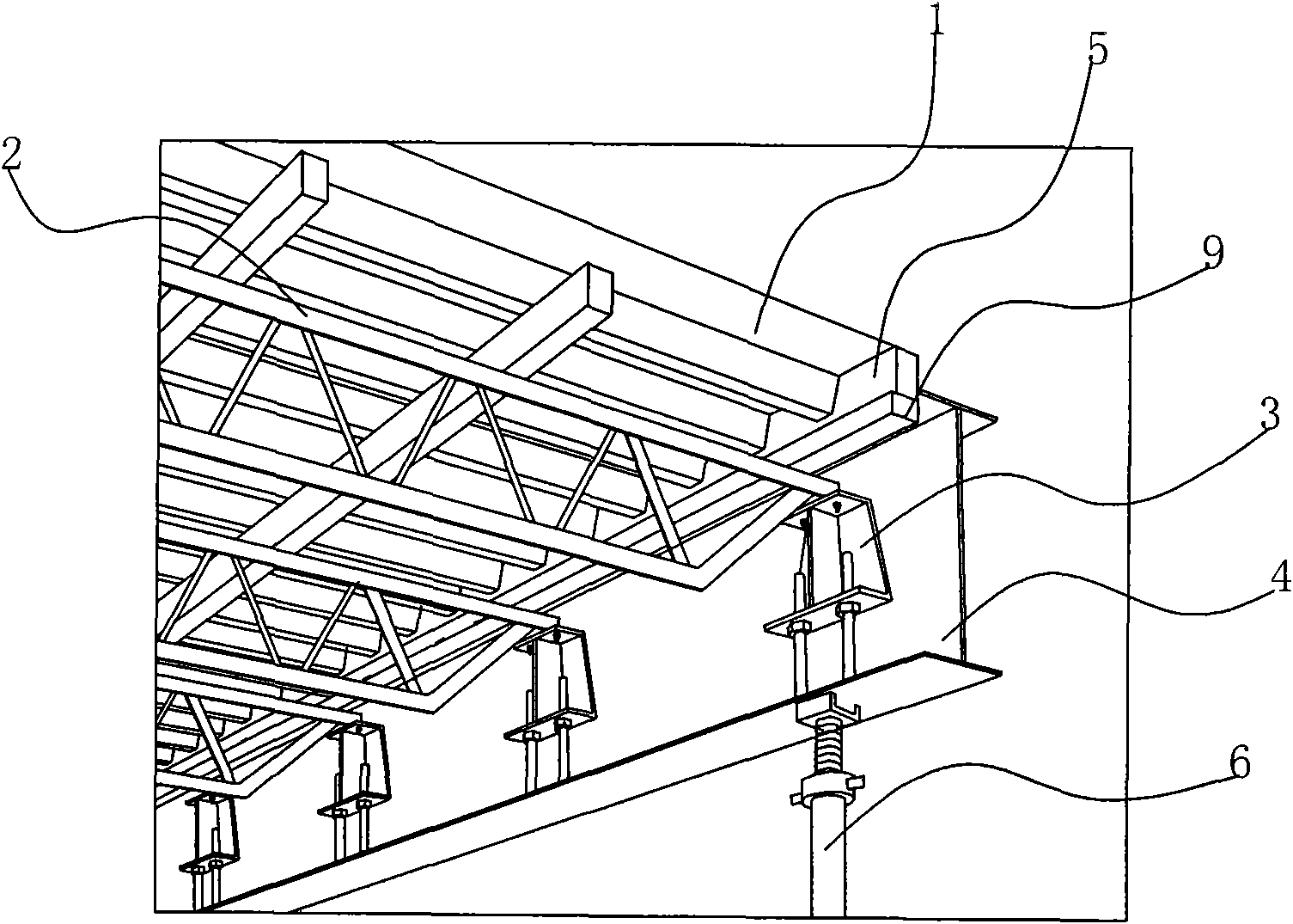
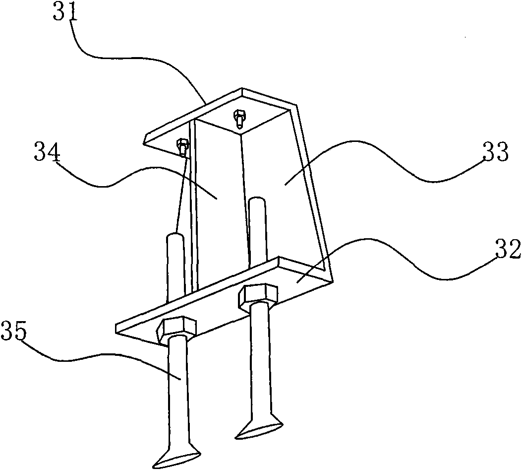
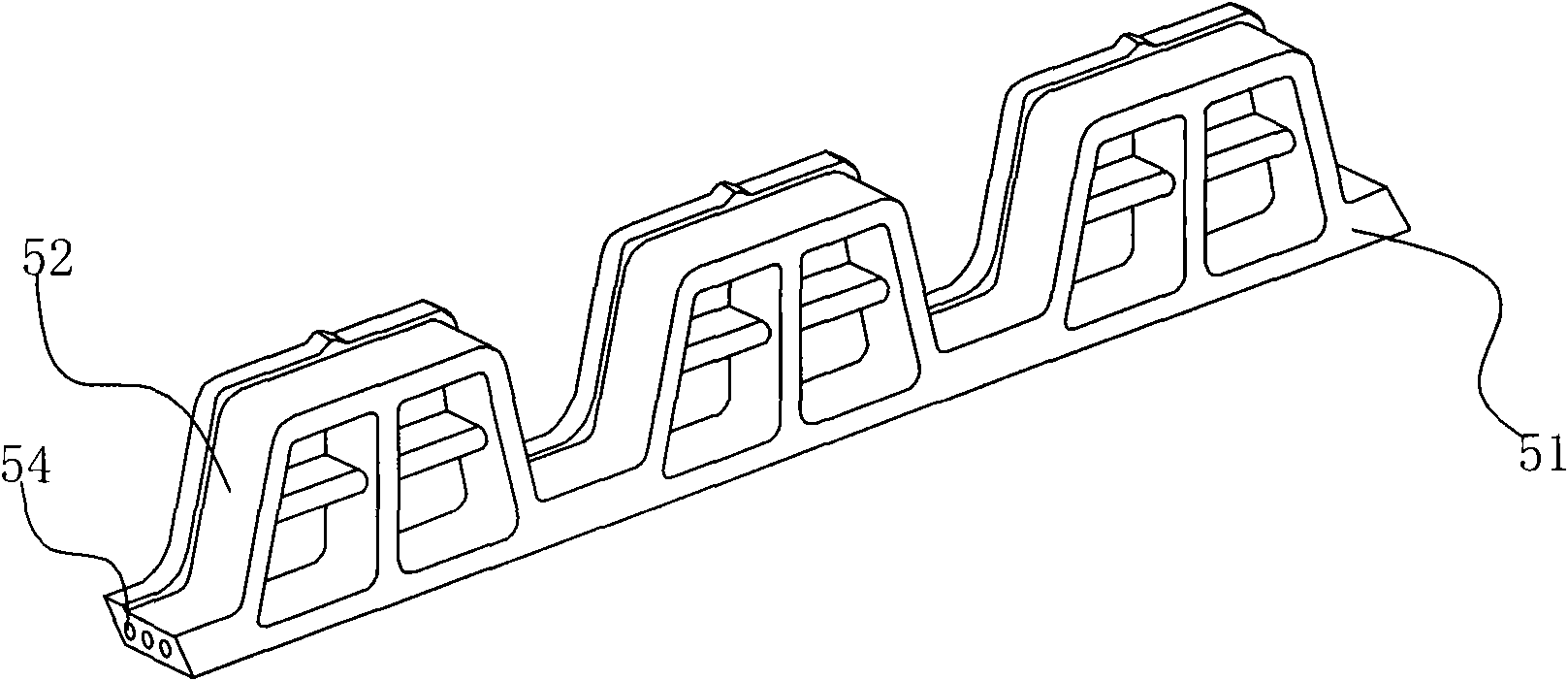
[0027] see Figure 1 to Figure 5 As shown in the figure, the cast-in-place floor formwork system for large-span steel beams provided by the present invention includes a floor formwork 1, an adjustable truss 2, and an adjustable shelving support 3 supporting the truss 2. The adjustable truss 2 is on the A grating 9 is laid, the floor formwork 1 is laid on the grating 9 , and the adjustable resting support 3 is arranged on the lower flange of the I-beam 4 . The adjustable truss 2 is a telescopic composite truss, and the adjustable truss 2 is connected wi...


PUM


Abstract

The invention discloses a long-slab-span steel beam cast-in-situ floor formwork system, which comprises a floor template, an adjustable truss and an adjustable placement support seat for supporting the adjustable truss, wherein a grille is laid on the adjustable truss; the floor template is laid on the grille; the adjustable placement support seat is arranged on a lower flange of a transverse H-shaped steel beam; and the adjustable truss is a telescopic combined truss and is connected with the upper end of the adjustable placement support seat. Compared with the conventional normal truss formwork system, the long-slab-span steel beam cast-in-situ floor formwork system provided according to the invention has the advantages of adjustable span, adjustable height and suitability for different beam heights; the adaptability of the truss is greatly improved; and the formwork cost is greatly lowered.

Description

technical field [0001] The invention relates to a building system, in particular to a cast-in-place floor formwork system for large-span steel beams. Background technique [0002] Usually, the floor support is made of full-floor scaffolding, and the scaffolding is generally made of steel pipe scaffolding or wrist buckle type scaffolding, all of which need to be connected by vertical and horizontal horizontal rods to ensure stability. The setting of horizontal support and scissor support will bring problems such as inconvenient construction access, cumbersome assembly and disassembly, increasing the number of turnover materials, and increasing costs. [0003] In order to solve the above problems, the Chinese utility model patent with the publication number of CN2617859 entitled "Truss-type Support Formwork System" discloses a truss-type support formwork system, both ends resting on the installed steel structural steel beams, including several rows of trusses , Fix several wo...

Claims


Application Information

Patent Timeline
Patent Type & Authority Applications(China)
IPC IPC(8): E04G11/48E04G11/56
Inventor 杨峰
Owner 杨峰
Why Eureka
Try Eureka