Glass antenna
A glass antenna and glass surface technology, which is applied to antennas, antenna parts, independent antenna unit combinations, etc., to achieve the effect of reducing man-hours
- Summary
- Abstract
- Description
- Claims
- Application Information
AI Technical Summary
Problems solved by technology
Method used
Image

Examples
Embodiment 1
[0055] First, based on Figure 1 to Figure 6 Example 1 will be described.
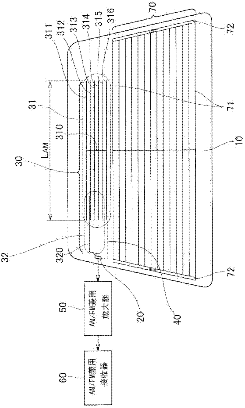
[0056] figure 1 It is a figure which shows the antenna pattern of the glass antenna of Example 1, Here, the antenna pattern of a side feeding is illustrated.
[0057] figure 1 Among them, the rear glass 10 is a glass surface of a rear window glass of a vehicle. The feeding point 20 is formed on the rear glass 10 and feeds power to each antenna pattern described later. Here, the feeding point 20 is formed at a side corner of the rear glass 10 (side feeding).
[0058] The AM / FM antenna unit 30 includes an AM antenna pattern 31 (first antenna pattern) that mainly receives the AM band and an FM antenna pattern 32 (second antenna pattern) that mainly receives the FM band.
[0059] The AM antenna pattern 31 includes a vertical conductor 310 extending vertically substantially at the center of the rear glass 10 and six horizontal conductors 311 to 316 perpendicular to the vertical conductor 310 and exten...
Embodiment 2
[0109] Below, refer to Figure 11 Example 2 will be described.
[0110] Figure 11 It is a figure which shows the antenna pattern of the glass antenna of Example 2.
[0111] like Figure 11 As shown, the glass antenna of Example 2 is in figure 1 The side feed antenna pattern shown in Example 1 has reception sensitivity adjustment elements 81 a , 81 b , and 81 c connected to part of the heater line 71 constituting the anti-fog heater 70 or the bus bar 72 . The reception sensitivity adjustment elements 81a, 81b, and 81c are connected to a part of the anti-fog heater 70, and the number and Any shape.
[0112] According to the glass antenna of the above-mentioned embodiment 2, in addition to the effect of the embodiment 1, after the AM / FM antenna pattern is formed by connecting the AM antenna pattern 31 and the FM antenna pattern 32 with the connecting wire 40, the receiving sensitivity is adjusted. The elements 81a, 81b, and 81c can finely adjust the receiving sensitivity,...
Embodiment 3
[0114] Below, refer to Figure 12 Example 3 will be described.
[0115] Figure 12 It is a figure which shows the antenna pattern of the glass antenna of Example 3.
[0116] like Figure 12 As shown, the antenna pattern of Example 3 is in Figure 4 The FM sub-antenna 90 is added to the upper antenna pattern of the first embodiment shown.
[0117] In addition, this FM sub-antenna 90 is capacitively coupled with the AM antenna pattern 31 similarly to the horizontal conductor 320 of the FM antenna pattern 32 constituting the AM / FM antenna unit 30. Figure 12 As shown, it is not necessary to form between the horizontal conductors 311 and 312 constituting the pattern 31 for the AM antenna, and it may be provided near the anti-fog heater 70, or may be formed by combining the mist heater 70 with the AM / FM antenna. The horizontal conductor 320 of the FM antenna pattern 32 of the portion 30 is capacitively coupled to form the FM sub-antenna 90 .
[0118] According to the above-me...
PUM
 Abstract
Description
Claims
Application Information
 - Generate Ideas
- Intellectual Property
- Life Sciences
- Materials
- Tech Scout
- Unparalleled Data Quality
- Higher Quality Content
- 60% Fewer Hallucinations
Browse by: Latest US Patents, China's latest patents, Technical Efficacy Thesaurus, Application Domain, Technology Topic, Popular Technical Reports.
© 2025 PatSnap. All rights reserved.Legal|Privacy policy|Modern Slavery Act Transparency Statement|Sitemap|About US| Contact US: help@patsnap.com