Combined driving micro-displacement regulation device

A combination of drive and adjustment device technology, applied in the direction of position/direction control, control/regulation system, non-electric variable control, etc., can solve the problems of unstable transmission, high noise, low transmission efficiency, etc., and achieve stable transmission and displacement , The effect of smooth displacement adjustment

Inactive Publication Date: 2013-02-13
TONGJI UNIV
View PDF2 Cites 0 Cited by
  • Summary
  • Abstract
  • Description
  • Claims
  • Application Information

AI Technical Summary

Problems solved by technology

[0005] The above mechanism meets the requirements of different occasions, but the single mechanical displacement adjustment device has many disadvantages such as poor dynamic performance, unstable transmission, and high noise due to the existence of more structural coupling; in addition, the single mechanical displacement Adjusting equipment often cannot achieve accurate and stable adjustment, and the equipment with accurate and stable adjustment has complex structure and expensive cost
Therefore, it is difficult for a single mechanical displacement adjustment device to meet the precise and stable adjustment requirements for micro-displacement of complex mechanisms.
[0006] Although a single hydraulic displacement adjustment device has stable transmission and simple operation, it is difficult to meet the precise adjustment requirements for micro-displacement of complex mechanisms due to its large energy loss and low transmission efficiency.

Method used


Image

  • Combined driving micro-displacement regulation device
  • Combined driving micro-displacement regulation device
  • Combined driving micro-displacement regulation device

Examples


Embodiment Construction

[0034] The combined drive micro-displacement adjusting device of the present invention will be further described below in conjunction with the accompanying drawings and embodiments, but this should not limit the protection scope of the present invention.

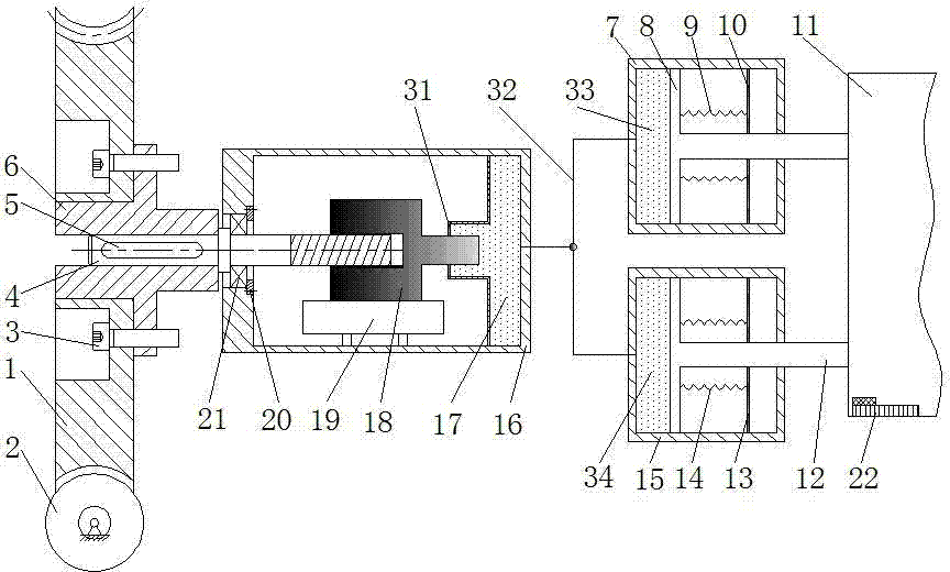
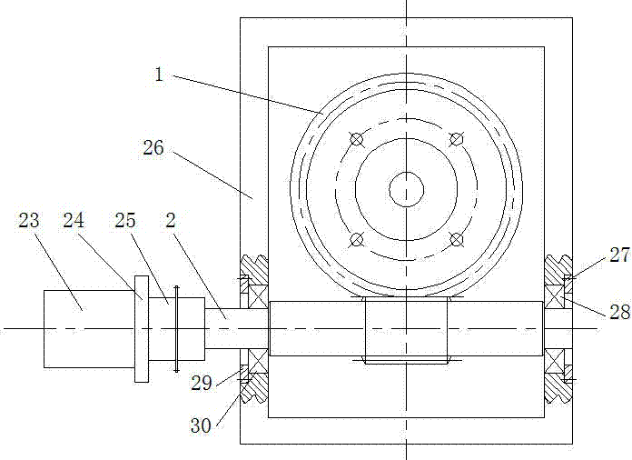
[0035]see first Figure 1-Figure 2 shown. figure 1 It is a cross-sectional view of the overall structure of the combined drive micro-displacement adjustment device of the present invention. figure 2 It is a partial view of the worm gear transmission module in the present invention. Depend on Figure 1-Figure 2 It can be seen that the combined drive micro-displacement adjustment device of the present invention includes a worm gear transmission module, a worm gear shaft 6, a rotating shaft 4, a screw 3, a key 5, a rolling bearing 21, a grating ruler 22, a bearing retaining ring 20, a nut 18, a slider 19, a shell Body 16, third oil cylinder 17, two hydraulic transmission modules and workbench 11. in:

[0036] The worm gea...


PUM


Abstract

The invention relates to a combined driving micro-displacement regulation device, which consists of a worm gear and worm drive module, a worm gear shaft, a rotating shaft, a key, a rolling bearing, a grating ruler, a bearing retainer, a slide block, a shell, a third oil cylinder, a hydraulic drive module, a worktable and a drive control system, wherein the worm gear shaft is fixedly connected with the worm gear and worm drive module through a screw; one end of the rotating shaft is connected with the worm gear shaft and the other end of the rotating shaft is connected with a nut screw thread pair; the rotating shaft is positioned in the rolling bearing; the bottom end of a nut is in rigid connection with the slide block; the slide block linearly reciprocates along a guide rail; the right end of the nut is provided with an equivalent piston and is connected with the third oil cylinder; the third oil cylinder is positioned in the shell and is communicated with an oil cylinder of the hydraulic drive module through a hydraulic circuit; a piston of the hydraulic drive module is connected with the worktable; the grating ruler is arranged on the worktable; and the worm gear and worm drive module consists of a motor, a motor bracket, a coupler, a worm-gear case, a first radial bearing, a first retainer ring, a second radial bearing, a second retainer ring, a worm gear and a worm. By the device, precise displacement of the worktable can be regulated, stable displacement regulation is realized, and a reduction ratio of static hydraulic drive is regulated.

Description

technical field [0001] The invention relates to a displacement adjustment device, in particular to a combined drive micro-displacement adjustment device. Background technique [0002] Precision displacement adjustment has a wide range of applications in precision machinery manufacturing, micro-electromechanical systems, optical component adjustment, robotics, and other fields. Mechanical displacement adjustment devices are widely used, and have the advantages of simple structure and convenient operation and control. Common mechanical displacement adjustment methods include: (1) double screw drive; (2) differential screw drive; (3) multi-stage precision gear Transmission; (4) worm gear mechanism, etc. [0003] In the prior technology (He Yusheng and other patents, application number: 03203863.1, application date February 2003 "A Micro-displacement Adjustment Device"), the adjustment device is composed of a fixed ring, an adjustment ring and a displacement ring. The pitch di...

Claims


Application Information

Patent Timeline
Patent Type & Authority Patents(China)
IPC IPC(8): G05D3/00
Inventor 李安虎李志忠张氢卞永明姜旭春
Owner TONGJI UNIV
Why Eureka
Try Eureka