
Self-operated T-shaped pneumatic rapid cut-off valve

A quick cut-off, self-operated technology, applied in the direction of valve lift, valve detail, valve device, etc., can solve problems such as easy wear, wear, and impact on service life

Inactive Publication Date: 2012-04-11
HANGZHOU FANGYUAN PLASTICS MASCH CO LTD
View PDF5 Cites 0 Cited by
  • Summary
  • Abstract
  • Description
  • Claims
  • Application Information

AI Technical Summary

Problems solved by technology

Based on the above, the traditional cut-off valve has an obvious upper limit limit for each medium controlled by the valve.
There is a new type of differential pneumatic shut-off valve in which the flow direction of the medium and the direction of the pneumatic actuator are Y-shaped, and the movable guide is set under the sealing seat, and the contact friction with the sealing seat causes friction
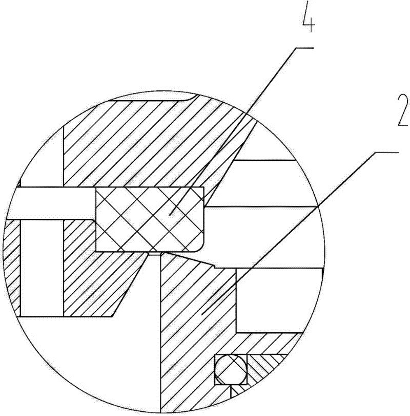
The valve seat of the original product is flat and in contact with the inclined surface of the sealing seat, which is easy to wear and affects the service life

Method used


Image

  • Self-operated T-shaped pneumatic rapid cut-off valve
  • Self-operated T-shaped pneumatic rapid cut-off valve
  • Self-operated T-shaped pneumatic rapid cut-off valve

Examples


Embodiment Construction

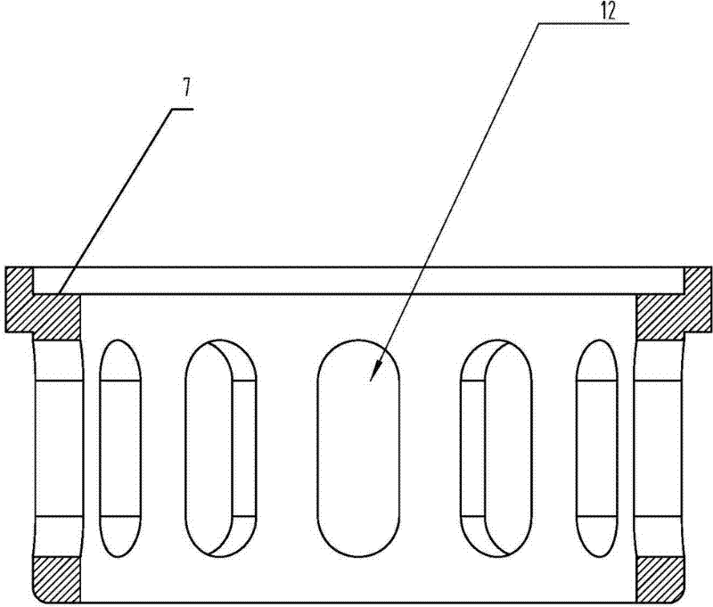
[0011] like Figure 1-Figure 3 As shown, the self-operated T-type pneumatic quick cut-off valve includes valve body 1, valve seat 2, pneumatic actuator head 9, piston rod 10, sealing ring 6, connecting body 8, spring 11, valve body 1 is provided with a valve seat 2. A cylinder liner 5 is provided on the valve seat 2, a sealing seat 4 is provided between the valve seat and the cylinder liner, a sealing seat gland 3 is provided on the sealing seat 4, and a cylinder liner is provided between the top of the cylinder liner and the valve body 1 The guide sleeve 7, that is, the cylinder liner guide sleeve 7 is set above the sealing seat 4; the valve seat at the contact point between the valve seat 2 and the sealing seat 4 is designed as an inclined plane, and the plane of the sealing seat is in line contact; the inner side of the cylinder liner guide sleeve passes through the seal The ring 6 is connected to the connecting body 8 . The cylinder liner guide sleeve 7 is provided with a...


PUM


Abstract

The invention relates to a control valve applicable to steam pulse constant-pressure heating of EPS (Expanded Polystyrene), EPP (Expanded Polypropylene) and EPO (Expanded Polyolefin) foam plastic machinery, in particular to a self-operated T-shaped pneumatic rapid cut-off valve which is characterized in that a valve seat is arranged in a valve body, a cylinder cover is arranged on the valve seat, a sealing base is arranged between the valve seat and the cylinder cover, a guide cover of the cylinder cover is arranged between the upper side of the cylinder cover and the valve body, namely, the guide cover of the cylinder cover is arranged above the sealing base, the inner side of the guide cover of the cylinder cover is connected with a connecting body through a sealing part, the valve seat at the contact part of the valve seat and the sealing base is an inclined plane, and the sealing base is a plane, and the inclined plane of the valve seat is in line contact with the plane of the sealing base. The rapid cut-off valve can be turned on under 20% of acting force of the similar valves, the on / off response speed is high, the volume is small, the control accuracy is high, the damage to the sealing surface is not affected in movement, the friction is reduced, and the service life is greatly prolonged.

Description

technical field [0001] The invention relates to a control valve suitable for EPS, EPP, EPO foamed plastic mechanical steam pulse constant pressure heating or the use of large flow and constant pressure compressed air. Background technique [0002] Because the switch of original shut-off valve is guaranteed by the active force of cylinder and spring completely. The waterproof hammer base imports the medium, although when the compressed air is relatively low, it is easier to open. However, when the pressure of the controlled medium is greater than the preload of the spring, the valve opens, resulting in a loss of control. If the inlet is on the seat, when the force generated by the pressure of the air medium is greater than the force generated by the cylinder, the valve will not be easy to open. Moreover, the traditional pneumatic shut-off valves have large actuator heads. For example, the bore of the cylinder of the cut-off valve actuator head of Φ65 diameter is Φ125. B...

Claims


Application Information

Patent Timeline
IPC IPC(8): F16K31/12F16K1/00
Inventor 袁健华袁国清章浙根
Owner HANGZHOU FANGYUAN PLASTICS MASCH CO LTD
Learn More