
Electronic expansion valve

A technology for electronic expansion valves and shells, which is applied in the direction of valve lifts, valve devices, and valve details, etc., can solve the problems of large radial size, high valve body height, unfavorable volume miniaturization of electronic expansion valves, etc., and achieve radial size reduction Effects of smallness, height reduction, and volume miniaturization

Active Publication Date: 2014-03-19
ZHEJIANG SANHUA INTELLIGENT CONTROLS CO LTD
View PDF6 Cites 0 Cited by
  • Summary
  • Abstract
  • Description
  • Claims
  • Application Information

AI Technical Summary

Problems solved by technology

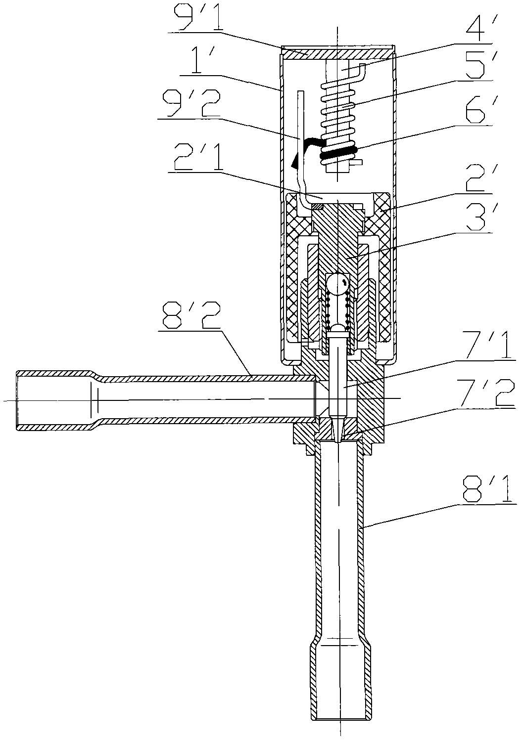
[0006] The stop rod 9'2 must be fixed on the magnet 2' and the screw rod 3', so as to drive the slip ring 6' to rotate around the guide rail 5'; since the stop rod 9'2 has a large axial dimension and there is no guide above it, therefore The rocking of magnet 2' will drive the stop bar 9'2 to shake. In order to prevent the stop bar 9'2 from interfering with the guide rail 5', a larger gap needs to be set between the stop bar 9'2 and the guide rail 5'. The radial size of the stopper component composed of the stopper rod 9'2, the guide rail 5', the slip ring 6' and the mandrel 4' is relatively large, so that it cannot be completely or mostly installed in the magnet cavity 2'1 of the magnet 2' In this way, the height of the entire valve body is relatively large, which is not conducive to the miniaturization of the electronic expansion valve.

Method used


Image

  • Electronic expansion valve
  • Electronic expansion valve
  • Electronic expansion valve

Examples


Embodiment Construction

[0055] The core of the present invention is to provide an electronic expansion valve. The electronic expansion valve can effectively reduce the height of the valve body on the basis of ensuring the working reliability, so as to achieve the purpose of miniaturization of the electronic expansion valve.

[0056] In order to enable those skilled in the art to better understand the technical solutions of the present invention, the present invention will be further described in detail below in conjunction with the accompanying drawings and specific embodiments.

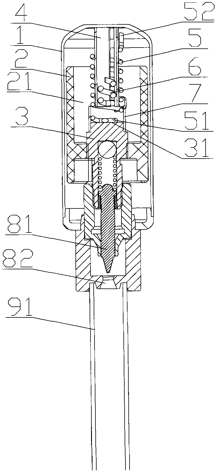
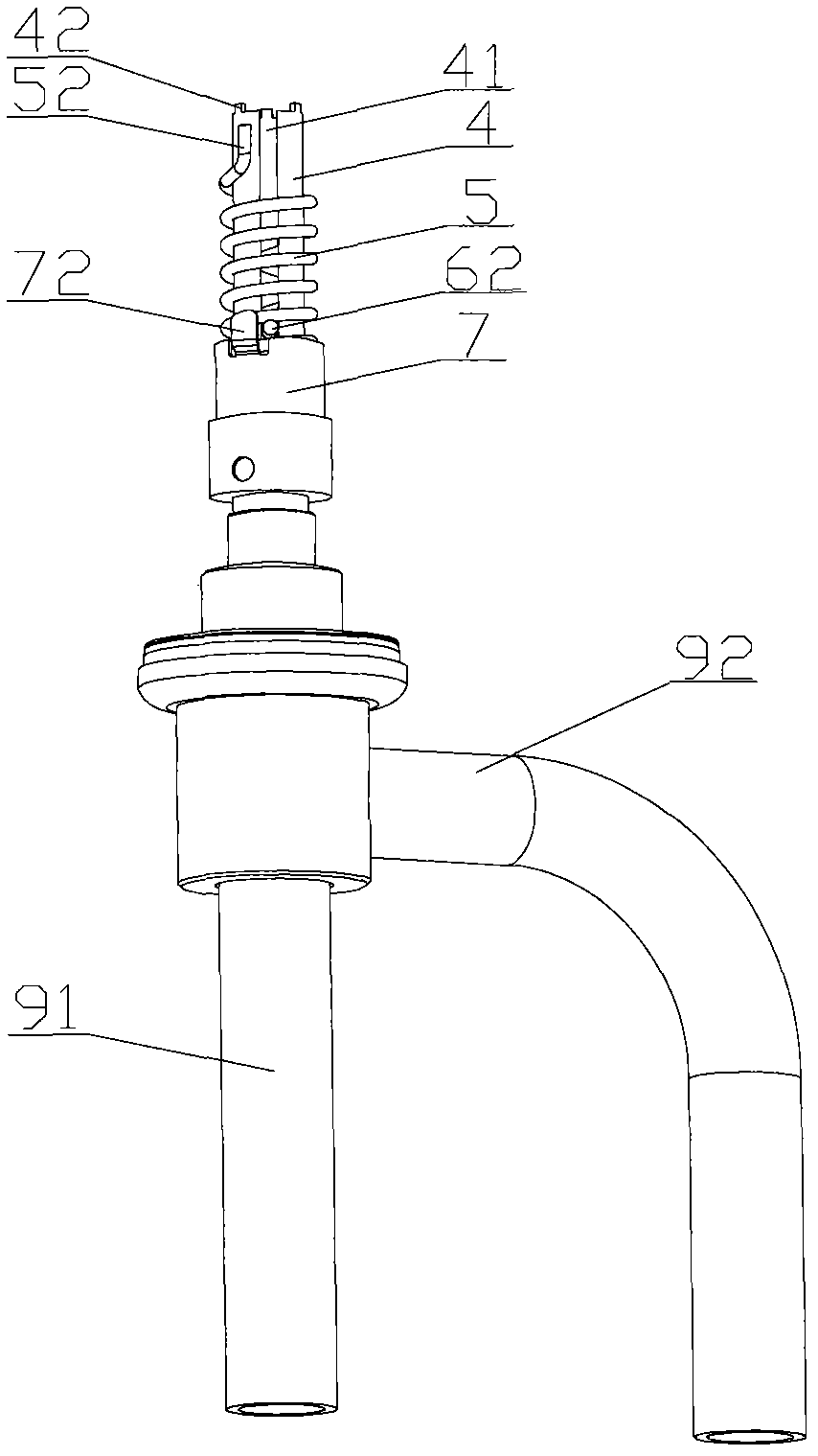
[0057] Please refer to figure 2 , image 3 , Figure 4 and Figure 5 , figure 2 It is a schematic structural diagram of the electronic expansion valve when the valve needle is fully opened in the first embodiment of the present invention; image 3 for figure 2 Schematic diagram of cooperation between the slip ring of the electronic expansion valve and the first stop part of the positioning sleeve; Figure 4 It is a...


PUM


Abstract

An electronic expansion valve comprises a housing (1), a magnet (2) and a lead screw (3). The electronic expansion valve further includes a mandrel (4) provided in the housing, a guide rail (5) provided on the outer side of the mandrel (4), and a slip-ring (6) matched up with the guide rail (5). One of the guide rail (5) and the mandrel (4) is connected with the lead screw (3) and rotates with the lead screw (3), and the other is connected with the housing (1). The guide rail (5) is connected with the lead screw (3) or the housing (1) by a positioning component. The slip-ring (6) is movably connected with the mandrel (4) along the axial direction of the mandrel (4) and is fixed to the circumference of the mandrel (4) to restrict the number of turns of the guide rail (5) or the mandrel (4). The electronic expansion valve enables effective reduction of the height of the valve body on the basis of the operational reliability.

Description

technical field [0001] The invention relates to the technical field of fluid control components, in particular to an electronic expansion valve. Background technique [0002] The electronic expansion valve for air conditioner is composed of four main parts: stepping motor, screw mechanism, stopper component, valve needle and valve port flow regulating mechanism. The stopper part is composed of a fixed part and a movable part. The movable part is fixed on the magnet, and can rotate circumferentially and lift axially with the magnet. The fixed part cooperates with the movable part, and its function is to limit the axial lifting stroke of the threaded mechanism and the valve needle, and prevent the threaded mechanism and the valve needle from excessively rising or falling, resulting in loss of flow regulation function. Electronic expansion valves for air conditioners are generally used on outdoor units of inverter air conditioners. In recent years, some high-end air conditione...

Claims


Application Information

Patent Timeline
Patent Type & Authority Patents(China)
IPC IPC(8): F16K31/06F16K1/00
CPCY02B30/72F25B41/062F25B2341/065Y02B30/70F25B41/34F25B41/30F16K31/50F16K27/02
Inventor 吕铭
Owner ZHEJIANG SANHUA INTELLIGENT CONTROLS CO LTD
Learn More