Method for installing telescopic shifting finger sleeve of harvester cutting table drum and telescopic shifting finger device

An installation method and harvester technology, applied to harvesters, agricultural machinery and implements, applications, etc., can solve the problem that the ear of grain cannot be turned out again, and achieve the effect of reducing the ear of grain and reducing power loss

Inactive Publication Date: 2012-04-11
株洲联合收割机有限公司
View PDF7 Cites 2 Cited by
  • Summary
  • Abstract
  • Description
  • Claims
  • Application Information

AI Technical Summary

Problems solved by technology

In the inertial separation box, the long stalks are compacted by the pressing bar and grasped by the fingers that act synchronously with it, and are forced to be sent to the axial flow drum for re-detachment, cross-flow fan for initial cleaning, and then sieved by the vertical drum sieve and The ring-shaped suction flow sucks and cleans impurities; but the patent does not specifically describe the installation method and structure of the finger, so it still cannot solve the problem of turning the ears of grain transferred to the entrance of the conveying device out again
[0005] In the domestic patent literature search, no other patent literature reports related to the technology of the present invention have been found, so it is necessary to improve this

Method used


Image

  • Method for installing telescopic shifting finger sleeve of harvester cutting table drum and telescopic shifting finger device
  • Method for installing telescopic shifting finger sleeve of harvester cutting table drum and telescopic shifting finger device
  • Method for installing telescopic shifting finger sleeve of harvester cutting table drum and telescopic shifting finger device

Examples


Embodiment Construction

[0022] The present invention will be further described below in conjunction with the accompanying drawings.

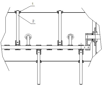
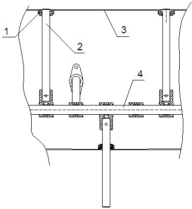
[0023] attached figure 2 An embodiment of the present invention is given, and it can be seen from the accompanying drawings that the present invention relates to an installation method of the retractable finger cover of the header drum of a harvester. The telescopic finger cover is placed on the telescopic finger, and the telescopic finger cover is installed simultaneously On the harvester header drum, it is characterized in that the telescopic finger sleeve is installed from the inner surface of the harvester header drum to the harvester header drum wall. This will reduce the taking out of ears of grain, reduce repeated work, thereby reducing the power loss of the harvester and reaching the basic purpose of the present invention.

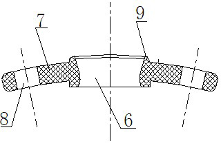
[0024] As a further improvement of the present invention: the top of the telescopic dial finger sleeve has a slit, and the outer diamete...


PUM


Abstract

The invention discloses a method for installing a telescopic shifting finger sleeve of a harvester cutting table drum and a telescopic shifting finger device. The telescopic shifting finger sleeve is sleeved on a telescopic shifting finger and installed on the harvester cutting table drum at the same time, and the telescopic shifting finger sleeve is installed on the wall of the harvester cutting table drum from the inner surface of the harvester cutting table drum. The telescopic shifting finger device comprises the harvester cutting table drum, the telescopic shifting finger, the telescopic shifting finger sleeve and a telescopic shifting finger driving mechanism; the telescopic shifting finger and the telescopic shifting finger driving mechanism are installed in the harvester cutting table drum, and the telescopic shifting finger stretches and retracts under the drive of the telescopic shifting finger driving mechanism during rotating together with the harvester cutting table drum; and the telescopic shifting finger sleeve is a lantern ring with a fixed lug, the upper part of the lantern ring is provided with a seam allowance, the outside diameter of the seam allowance is matched with the size of a hole, which is used for installing the telescopic shifting finger sleeve, of the harvester cutting table drum, the telescopic shifting finger sleeve is installed in the hole from the inner surface, and the outer end face of the seam allowance of the installed telescopic shifting finger sleeve is 0.5 to 1 millimeter higher than that of the cutting table drum.

Description

technical field [0001] The invention relates to a component installation method and device of an agricultural full-feed combine harvester, in particular to an installation method and device for a telescopic finger sleeve of a header drum of an agricultural full-feed combine harvester. It belongs to the field of agricultural machinery. Background technique [0002] At present, the header drum devices of full-feed combine harvesters produced by various harvester manufacturers mostly use telescopic finger devices through the rotation of the header drum, and some of them use telescopic dials to bring the cut ears into the feeder. to the transmission device. Wherein, the telescopic finger device is to install the telescopic finger on the header drum device, and the corn ear will be cut into the transmission device by the telescopic finger; the telescopic finger of the existing header drum device is installed on the cutting The outside of the table drum, and the telescopic finge...

Claims


Application Information

Patent Timeline
Patent Type & Authority Applications(China)
IPC IPC(8): A01D57/01
Inventor 余新胜李宁冯振科刘建洪陈汉华洪军毅陈国军钱旭华刘君华付建新刘兴国
Owner 株洲联合收割机有限公司
Why Eureka
Try Eureka