
Heating element

A technology of heating elements and heating zones, applied in the direction of furnace heating elements, heating element materials, electric furnace heating, etc., can solve problems such as terminal connection problems

Inactive Publication Date: 2012-04-04
SANDVIK INTELLECTUAL PROPERTY AB
View PDF7 Cites 9 Cited by
  • Summary
  • Abstract
  • Description
  • Claims
  • Application Information

AI Technical Summary

Problems solved by technology

Conversely, deep heating of the terminals can e.g. cause problems with the connection of the terminals to the leads

Method used


Image

  • Heating element
  • Heating element
  • Heating element

Examples


Embodiment Construction

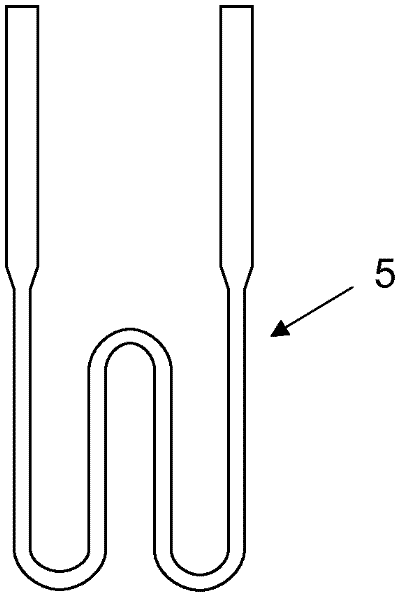
[0026] figure 1 An embodiment of a heating element 1 is shown comprising a heating zone 3 and two terminals 2 in each end of the heating zone 3 . The heating element 1 shown is a two-handled U-shaped heating element. However, the heating element of the invention may also have other shapes, for example a four-handled heating element, a helical heating element or a heating element with a straight heating zone. A heating element may also have more than one heating zone and more than two terminals. Additionally, the heating zone may be divided into a plurality of heating zones.

[0027] exist figure 1 , the terminals 2 each have a diameter D that is larger than the diameter d of the heating zone. It should however be noted that the terminal 2 may have substantially the same diameter as the heating zone 3 .

[0028] As disclosed above, molybdenum disilicide-based materials comprising an oxide phase were previously known for use as heating elements. Other non-conductive compou...


PUM


Abstract

A heating element for use in industrial furnaces and which enables the use of a higher voltage over the element is disclosed. The heating element comprises a heating zone made of a molybdenum disilicide based material comprising 48-75 % by volume of oxide phase and two terminals made of a molybdenum disilicide based material comprising up to 25 % by volume of oxide phase.

Description

technical field [0001] The present invention generally relates to a heating element of the molybdenum disilicide type comprising at least one heating zone and two terminals. More specifically, it relates to heating elements comprising a heating zone made of a molybdenum disilicide-based material. Background technique [0002] Heating elements of molybdenum disilicide material are widely used in industrial furnaces operating at relatively high temperatures, eg above 1000°C, because they can withstand oxidation at such high temperatures. The oxidation resistance is due to the formation of a thin and sticky protective layer of silica glass on the surface. [0003] Examples of this type of heating element are in figure 1 exemplifies. The heating element 1 is a double-handled element and comprises a diameter d and length L e The heating zone 3, and two diameter D and length L u The terminals 2 are arranged at each end of the heating zone 3 . The twin handles are substantial...

Claims


Application Information

Patent Timeline
Patent Type & Authority Applications(China)
IPC IPC(8): C04B35/58H05B3/14
CPCC04B2235/3418H01C17/0656C04B35/18C04B35/58C04B2235/3463C04B2235/3217H05B3/24C04B2235/3891C04B2235/80C04B2235/77C04B35/185C04B2235/349H05B3/141H05B3/62C04B2235/3256C04B35/58092H05B3/14F27D11/00
Inventor 马茨·松德贝里埃里克·斯特伦
Owner SANDVIK INTELLECTUAL PROPERTY AB
Learn More