
Illumination control system utilizing microcontroller and illumination control method

A lighting control system and micro-controller technology, applied in lighting devices, energy-saving lighting, light sources, etc., can solve the problems of increased power consumption, high production costs, and cumbersome circuit assembly, and achieve simplified circuits, energy saving, and simple circuits Effect

Active Publication Date: 2012-04-04
陈家德
View PDF6 Cites 12 Cited by
  • Summary
  • Abstract
  • Description
  • Claims
  • Application Information

AI Technical Summary

Problems solved by technology

[0005] However, the technologies mentioned in the previous two examples use a lot of operational amplifiers and digital-analog hybrid circuits, resulting in cumbersome circuit assembly. In addition to high production costs, it also increases power consumption.
For example, in the standby state, it is measured that the dimming system of US 5598066 consumes more than 30W of electric power, which is close to the electric power of the light source load at low brightness, so the dimming system does not meet the requirements for saving electric energy

Method used


Image

  • Illumination control system utilizing microcontroller and illumination control method
  • Illumination control system utilizing microcontroller and illumination control method
  • Illumination control system utilizing microcontroller and illumination control method

Examples


Embodiment Construction

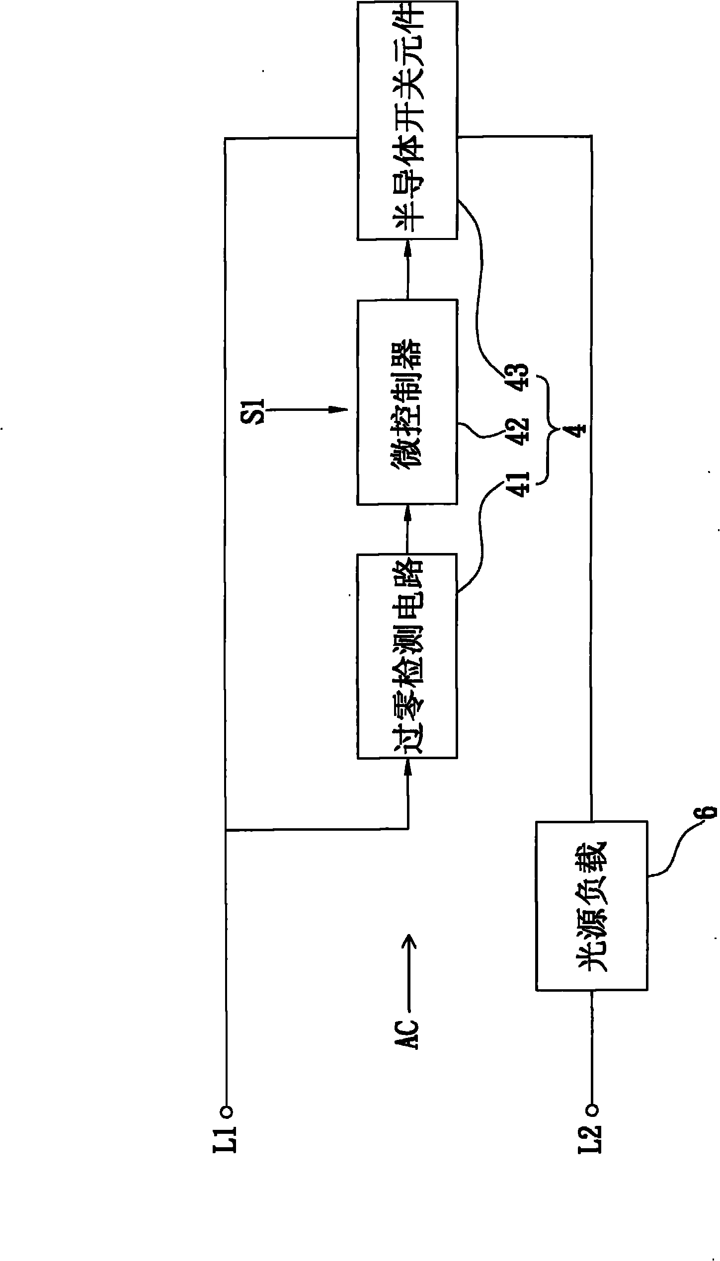
[0044] refer to figure 2 . figure 2 It is a schematic diagram of the lighting control system according to the first embodiment of the present invention. The lighting control system mainly includes a zero-crossing detection circuit 41 , a microcontroller 42 , and a semiconductor switching element 43 , and these three units form the dimming circuit 4 . In addition, the lighting control system is also provided with an external control signal S1 sent to the microcontroller 42 . like figure 2 shown. One terminal of the semiconductor switching element 43 is connected to a lead L1 of the AC power supply AC, and its other terminal is connected to another lead L2 of the AC power supply AC via the light source load 6. Therefore, the lighting control system of the present embodiment belongs to the connection line (on- line) dimming system. The microcontroller 42 mentioned below uses a one-time programmable (OTP) microcontroller as an implementation element, and the semiconductor ...


PUM


Abstract

The invention provides an illumination control system utilizing a microcontroller and an illumination control method. The illumination control system mainly comprises the microcontroller, a semiconductor switch element and a light source load. The microcontroller outputs zero crossing point delay pulses which are synchronous with a positive and negative half cycle of an alternating current power supply so as to trigger and control the conduction time interval of the semiconductor switch element, and switches and outputs zero crossing point delay pulses with different delay time according to external control signals so as to control the conduction time interval of the semiconductor switch element respectively to transfer different average electric power to the light source load, thereby enabling the light source load to output different illumination intensity. The illumination control system is suitable for light sources of different load types simultaneously, especially filament lamps, daylight lamps and alternating current light-emitting diodes.

Description

technical field [0001] The invention relates to a lighting control system and a lighting control method using a microcontroller, in particular to a lighting control system and a lighting control method using a microcontroller to adjust different electric power to a light source load. Background technique [0002] figure 1 It is a circuit functional block diagram of a traditional lighting control system. A traditional lighting control system mainly includes a dimming circuit 2 , which controls an AC power supply AC to transmit a certain value of electric power to a light source load 1 . The dimming circuit 2 includes a semiconductor switch element 20 and a phase trigger circuit 22 , and the semiconductor switch element 20 is usually a bidirectional controllable switch. The phase trigger circuit 22 generates trigger signals with different time differences by adjusting the variable resistors to control the conduction period of the semiconductor switching element 20 during pos...

Claims


Application Information

Patent Timeline
Patent Type & Authority Applications(China)
IPC IPC(8): H05B37/02H05B39/04H05B41/38
CPCY02B20/14Y02B20/00
Inventor 陈家德
Owner 陈家德
Learn More