
Motor

A motor and cover technology, which is applied in the field of electric motors, can solve the problems of increasing the number of parts, complicated motor assembly, etc., and achieve the effect of preventing electrification

Active Publication Date: 2014-08-06
NIDEC CORP
View PDF7 Cites 0 Cited by
  • Summary
  • Abstract
  • Description
  • Claims
  • Application Information

AI Technical Summary

Problems solved by technology

In the means disclosed in Japanese Patent Application Laid-Open No. 11-75337, the number of components increases
Also, the assembly of the motor becomes cumbersome

Method used


Image

  • Motor
  • Motor
  • Motor

Examples


Embodiment Construction

[0018] In this manual, place the motor in figure 1 The upper side in is simply called "upper side", and the lower side is simply called "lower side". In addition, the up-down direction does not indicate the positional relationship or direction when incorporated into an actual device. In addition, the radial direction around the central axis is simply referred to as "radial direction".

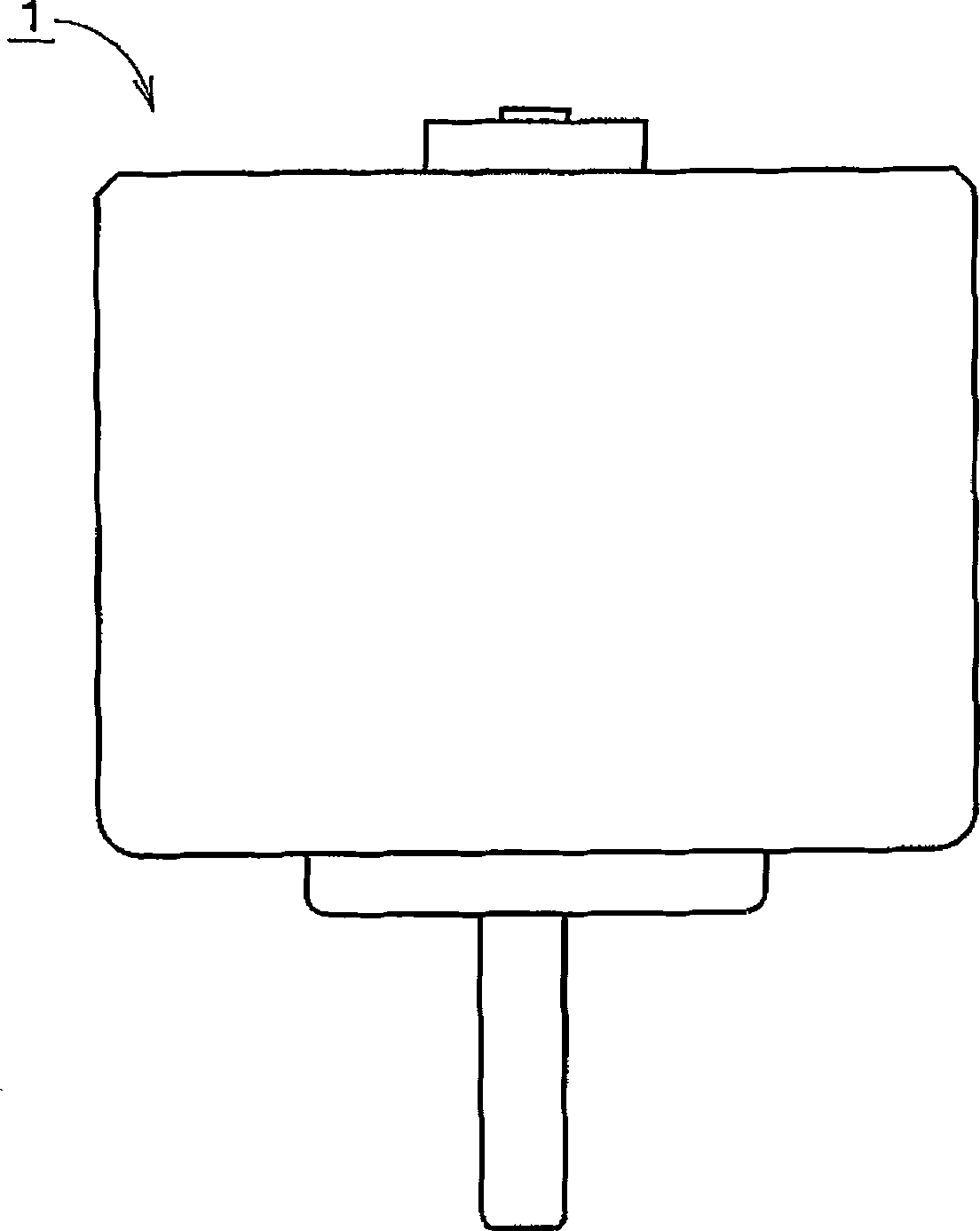
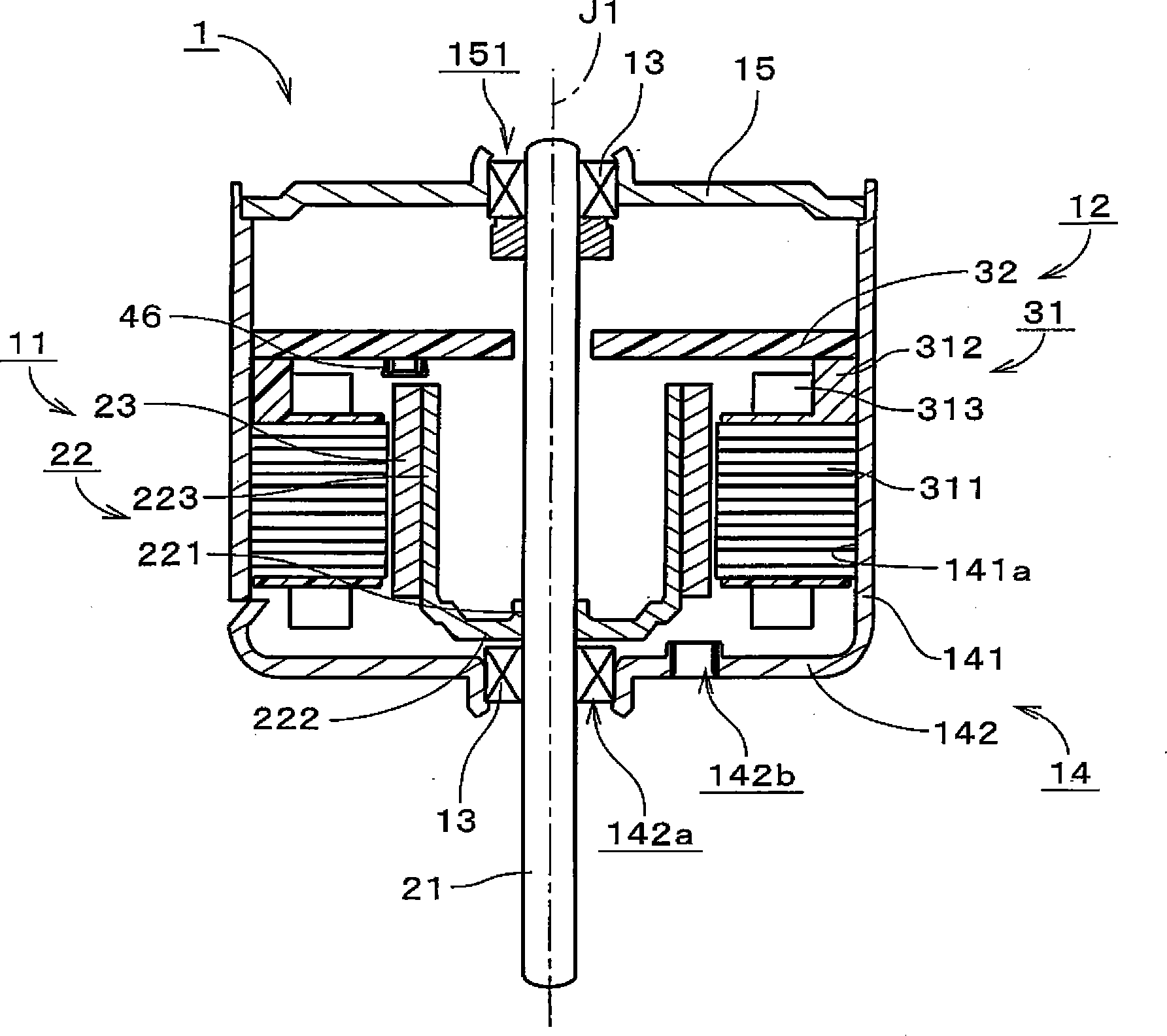
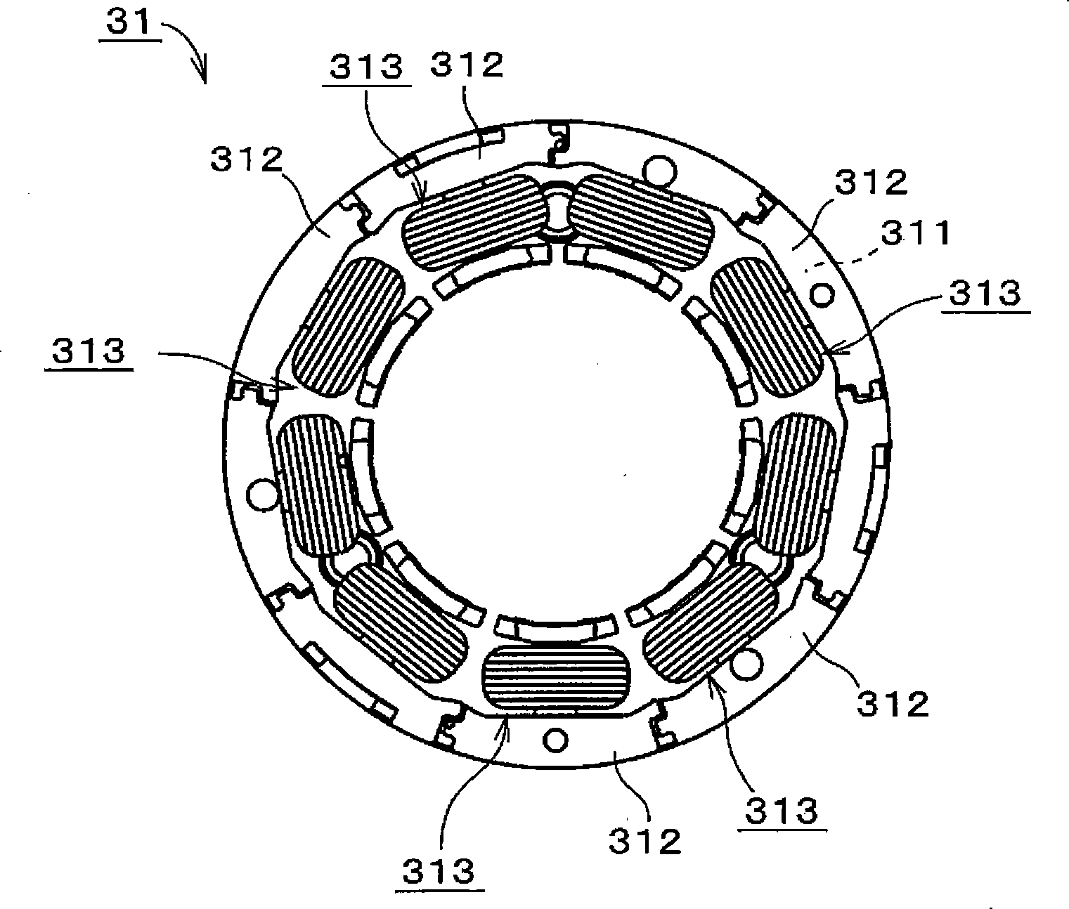
[0019] figure 1 It is a front view of the motor 1 which concerns on one exemplary embodiment of this invention. The motor 1 is installed in, for example, OA (Office Automation) equipment such as a printer and a time recorder, and equipment that conveys paper, such as a banknote validator. In this type of apparatus, the power of the motor 1 is used to convey paper. The motor 1 can also be mounted on a device that does not convey paper. figure 2 is a sectional view of the motor 1 . The motor 1 is an inner rotor type motor. The motor 1 includes a rotating portion 11 , a stationary portion ...


PUM


Abstract

PROBLEM TO BE SOLVED: To easily reduce or prevent electrostatic charge. SOLUTION: A motor includes a cover member 14 formed by a conductive material, a bearing part, a shaft, a rotor magnet rotating with the shaft, an annular stator facing the rotor magnet in the radial direction in the cover member, a circuit board 32 arranged perpendicular to a central axis J1 in the cover member, and an electric power line 431 and a ground line 432 connecting to the circuit board. The circuit board includes a conductive pattern 41 and an electronic component mounted on the conductive pattern, and the conductive pattern includes a driving circuit pattern 411 supplying electric power from the electric power line to the stator, a ground pattern 412 to which the ground line is connected, and a cover antistatic pattern 413 which is located closer to the cover member than the driving circuit pattern and the ground pattern or contacts with the cover member. The circuit board includes a resistance electrically connecting the ground pattern with the cover antistatic pattern. COPYRIGHT: (C)2012,JPO&INPIT

Description

technical field [0001] The present invention relates to electric motors. Background technique [0002] Conventionally, in various OA (Office Automation) equipment, an inner rotor type motor has been used as a drive source. The brushless motor disclosed in Japanese Unexamined Patent Application Publication No. 2005-229698 includes a substantially cylindrical case with a cover, a cover plate, a stator, a rotor magnet, a rotor yoke, and a rotating shaft. The housing has a cylindrical peripheral wall and an end plate provided at one end of the cylindrical peripheral wall. A cover plate is fixed to the other end of the housing. The stator is fixed to the inner peripheral surface of the cylindrical peripheral wall. A rotor yoke having a cylindrical portion and a cover portion is disposed inside the stator. A rotor magnet is fixed to the outer peripheral surface of the cylindrical portion of the rotor yoke. The rotor magnets face the stator. A rotating shaft is fixed to the c...

Claims


Application Information

Patent Timeline
Patent Type & Authority Patents(China)
IPC IPC(8): H02K11/00H02K5/04
Inventor 原田浩二张广祥
Owner NIDEC CORP
Learn More