Lighting device for improvement of light performance of borehole television

A technology for drilling TVs and lighting devices, which is applied to lighting devices, components of lighting devices, lighting applications, etc. It can solve the problems of poor overall image quality, bright and dark images, bright and dark light, etc., to achieve reasonable structure, Consistent brightness and good effect

Inactive Publication Date: 2012-04-04
CHANGJIANG SURVEY PLANNING DESIGN & RES +2
View PDF8 Cites 1 Cited by
  • Summary
  • Abstract
  • Description
  • Claims
  • Application Information

AI Technical Summary

Problems solved by technology

[0002] In the drilling TV system, the lighting system of the previous camera is mainly sealed with a ring light (heat light source) and a light-transmitting cover. blurry image
In view of the above problems, people use LED cold light lamps instead of ring lights (hot light sources). Although this method solves the fogging phenomenon in the light-transmitting cover, but due to the LED itself, the point light source emits light at a certain angle, and the overlap of light in the light-transmitting cover The inconsistency of superimposition directly leads to uneven light, and the light irradiated on the wall of the drilled hole is bright and dark, resulting in a sense of light and dark in the image collected by the camera, and the overall quality of the image is poor

Method used


Image

  • Lighting device for improvement of light performance of borehole television
  • Lighting device for improvement of light performance of borehole television
  • Lighting device for improvement of light performance of borehole television

Examples


Embodiment Construction

[0009] The lighting device of the present invention will be further described in detail below in conjunction with the accompanying drawings

[0010] see Attachment

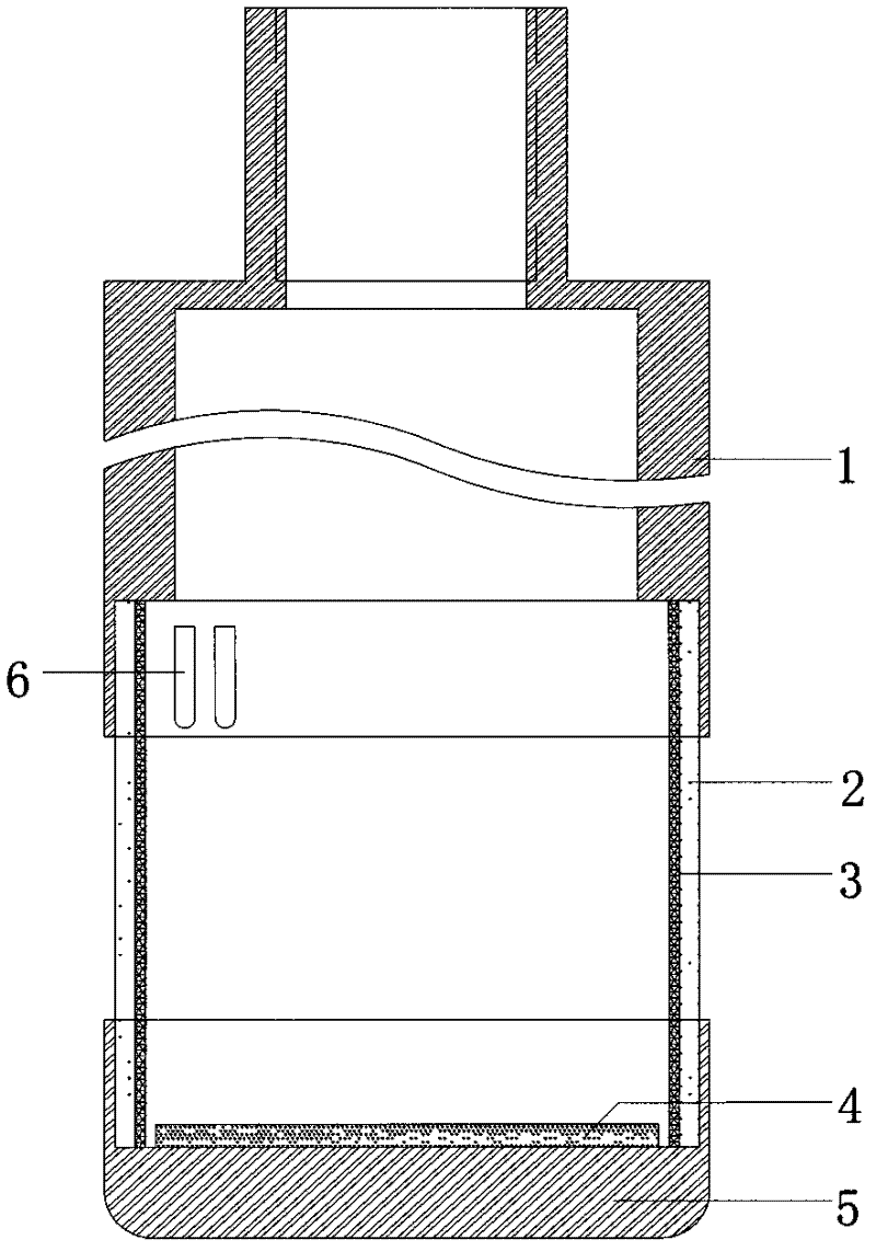
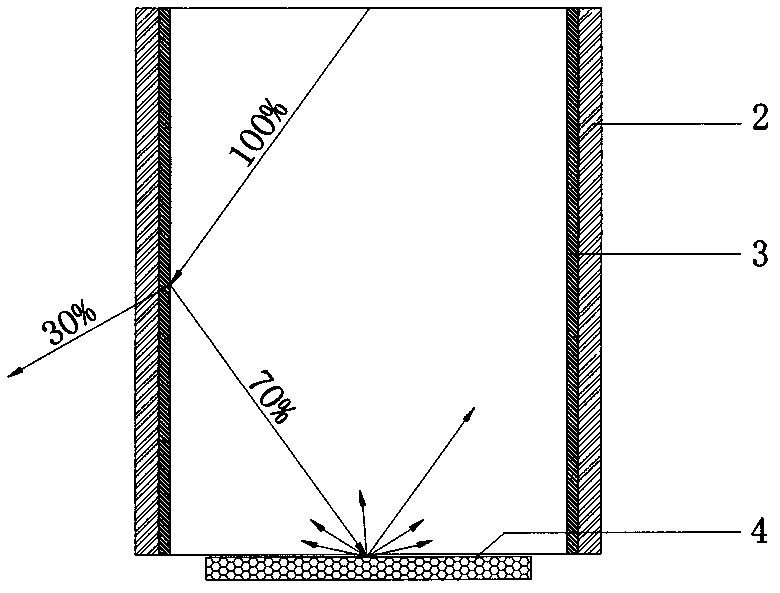
[0011] A lighting device for improving the lighting performance of a borehole TV. The lighting device is composed of a probe tube 1, a light-transmitting cover 2, a base 5, an LED lamp group 6, and an astigmatism pad 4. The upper end of the light-transmitting cover 2 is sealed and connected to the probe tube 1. The lower end of the light-transmitting cover 2 is sealed and connected to the base 5. The inner wall of the light-transmitting cover 2 is covered with a reflective layer 3. The reflective layer 3 is made of colorless and transparent nano-metal chrome-aluminum. The thickness of the reflective layer (3) is 8 ~ 10nm. The combination of the reflective layer 3 and the light-transmitting cover 2 can be completed by coating or film-sticking process. A light-scattering pad 4 is arranged at the bottom of the light...


PUM

PropertyMeasurementUnit
Thicknessaaaaaaaaaa

Abstract

The invention relates to a lighting device for improvement of light performance of a borehole television and belongs to the field of manufacturing engineering testing equipment. The lighting device consists of a probe, a light-transmittable shade, a base, an LED lamp set and a diffusion pad; a reflection layer is coated on the internal wall of the light-transmittable shade; the diffusion pad is arranged at the bottom of the light-transmittable shade, so that only the small part of the lights of the point light sources emitted by the LED lamp set is transmitted when radiating on the reflection layer, and the majority of the lights remain in the light-transmittable shade for next transmission and reflection; simultaneously, the partial lights is subjected to further diffuse reflection while radiating on the diffusion pad at the bottom of the light-transmittable shade, so that the purpose of obtaining uniform light rays is achieved after the light point sources emitted by the LED lamp set is sufficiently subjected to the reflection and the diffuse reflection for many times in the light-transmittable shade; the sufficient and uniform light rays irradiated on a camera are guaranteed, the light rays transmitted on the borehole wall are uniform and the image has no shade, uniform brightness and good clearness. The lighting device disclosed by the invention has a rational structure, practicability and convenience in installation, good effect and high efficiency.

Description

technical field [0001] The invention relates to an illuminating device for improving the illumination performance of a borehole TV, and belongs to the field of engineering testing equipment manufacturing. Background technique [0002] In the drilling TV system, the lighting system of the previous camera is mainly sealed with a ring light (heat light source) and a light-transmitting cover. The image is blurry. In view of the above problems, people use LED cold light lamps instead of ring lights (hot light sources). Although this method solves the fogging phenomenon in the light-transmitting cover, but due to the LED itself, the point light source emits light at a certain angle, and the overlap of light in the light-transmitting cover The inconsistency of superimposition directly leads to uneven light, and the light irradiated on the wall of the drill hole is bright and dark, resulting in a sense of light and dark in the image collected by the camera, and the overall quality ...

Claims


Application Information

Patent Timeline
IPC IPC(8): G03B15/05F21V7/22F21W131/402F21Y101/02
Inventor 张建清许新国陆二男张智刘方文刘润泽李文忠蔡加兴陈剑飞陈华陈敏魏仁新马圣敏谭显江
Owner CHANGJIANG SURVEY PLANNING DESIGN & RES
Why Eureka
Try Eureka