
Depositing and use separation station for a sheet punching press

A partially separated and useful technology, applied in the direction of transportation and packaging, container manufacturing machinery, carton/carton manufacturing machinery, etc., can solve problems such as production loss, and achieve the effect of increasing production capacity

Active Publication Date: 2015-05-06
天津长荣云印刷科技有限公司
View PDF12 Cites 0 Cited by
  • Summary
  • Abstract
  • Description
  • Claims
  • Application Information

AI Technical Summary

Problems solved by technology

The production of the die-cutter has to be interrupted in order to move the rake, which results in a production loss of about 5 to 10 sheets

Method used


Image

  • Depositing and use separation station for a sheet punching press
  • Depositing and use separation station for a sheet punching press
  • Depositing and use separation station for a sheet punching press

Examples


Embodiment Construction

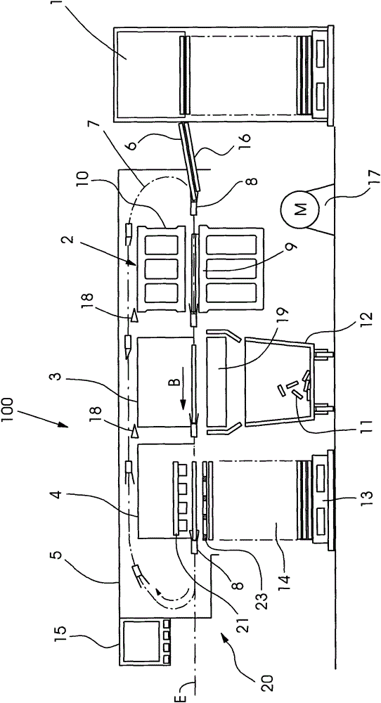
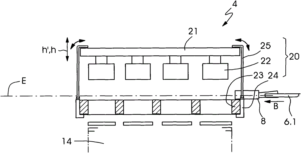
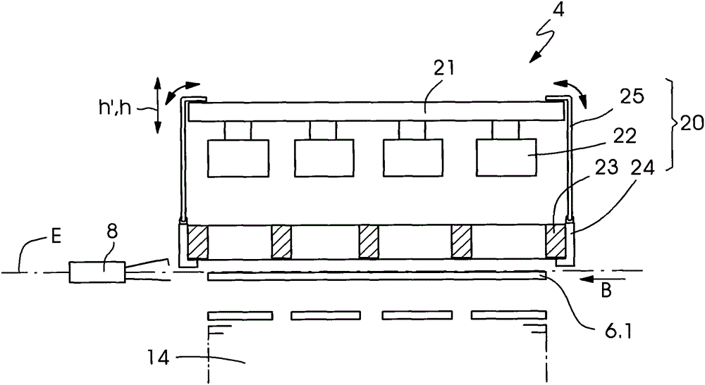
[0038] figure 1 The schematic design of a sheet die-cutting and embossing machine 100 for die-cutting, stripping and placing sheets made of paper, cardboard and the like is shown in FIG. The die-cutting and embossing machine 100 has a feeder 1, a die-cutting station 2, a stripping station 3 and a delivery 4 with a laying and useful part separation station 20, which consist of a common machine housing 5 carrying and surrounding. The processing stations 2 , 3 , 4 are accessible from one side, the so-called operator side; the drive train of the sheet-cutting and embossing machine 100 is located on the opposite side, the so-called drive side.

[0039] Sheets 6 are separated from a stack by a feeder 1 , fed to the sheet transport system 7 and gripped by grippers fixed to the gripper bridge of the gripper carriage 8 and moved along the The sheet transport direction B is intermittently drawn through the various stations 2 , 3 and 4 of the die-cutting and embossing machine 100 .

...


PUM


Abstract

The station (20) has a stroke movable lower tool (23) cooperating with a stroke movable upper tool (21) for separating copies of sheets, where the tools are coupled with each other by a coupling device. Sheets (6) are transported by a sheet transportation system (7) in a sheet transport plane (E) in the station. The coupling device is provided for temporary mechanical connection of the stroke movable lower tool with the upper tool. A machine drive (17) is connected with the stroke movable upper tool for stroke movement of the upper tool. Independent claims are also included for the following: (1) a flat bed sheet punching- and / or -embossing press comprising a depositing and copies separation station (2) a method for deposition of intermediate sheets on a delivery stack.

Description

technical field [0001] The invention relates to a depositing and useful part separating station, a sheet die-cutting and / or embossing machine and a method for depositing intermediate sheets. Background technique [0002] Cutting with a cutting die of a closed geometry, which can be round, oval or polygonal and any kind of irregular shape, is called "die cutting". Processes performed in post-press processing such as die-cutting with punches, corner cutting and index die-cutting also belong to this field. Die-cutting is carried out against a die-cutting block or against an impression, partly also a shearing process. Packaging materials made of paper, cardboard, cardboard or corrugated are mainly die-cut in sheet format. It is also possible to additionally apply stripe lines or arches in the useful part during the die-cutting process. This complex process makes it absolutely necessary that the sheets are die-cut individually. Since the final product involves extremely deman...

Claims


Application Information

Patent Timeline
Patent Type & Authority Patents(China)
IPC IPC(8): B31B1/14B31B3/14B26F1/40B26D7/18
CPCB26D7/1818B26D7/0633B26D7/32B26D7/325B26F1/38B26F1/40B65H29/041B65H2701/176B65H2701/1762B65H2701/18264B65H2801/42
Inventor D·埃尔巴M·帕祖赫
Owner 天津长荣云印刷科技有限公司
Learn More