Video encoding device and video decoding device

A technology for moving images and encoding devices, applied in image communication, digital video signal modification, electrical components, etc., can solve the problems of waste, difficulty in selecting small transform sizes, and increase in the amount of additional information code, so as to reduce the amount of processing, reduce The effect of code size

Inactive Publication Date: 2015-04-29
SHARP KK
View PDF1 Cites 0 Cited by
  • Summary
  • Abstract
  • Description
  • Claims
  • Application Information

AI Technical Summary

Problems solved by technology

However, a new problem arises in that the code amount of additional information required to select the partition size and transform size to be applied in decoding increases in each local area on the moving image.
However, since a large partition is likely to be selected in a region where the spatial correlation of pixel values ​​or motion vectors is high, when frequency transform with a small transform size is applied to such a partition, compared with the case of applying frequency transform with a large transform size , it is difficult to concentrate the energy of the prediction residual to a smaller number of transform coefficients
Therefore, the frequency transformation with small transform size is basically not selected, and the additional information required to select the transform size becomes wasteful
It becomes more difficult to choose a small transform size, especially if the maximum partition size is enlarged, thereby enlarging the size difference between the large partition size and the small transform size
[0026] In addition, in Non-Patent Document 2, the frequency transformation with the same size transformation size can be selected for the rectangular partition, but it does not mention what kind of criteria is used to determine the transformation that can be selected when the types of transformation sizes are further increased. size

Method used


Image

  • Video encoding device and video decoding device
  • Video encoding device and video decoding device
  • Video encoding device and video decoding device

Examples


Embodiment approach 1

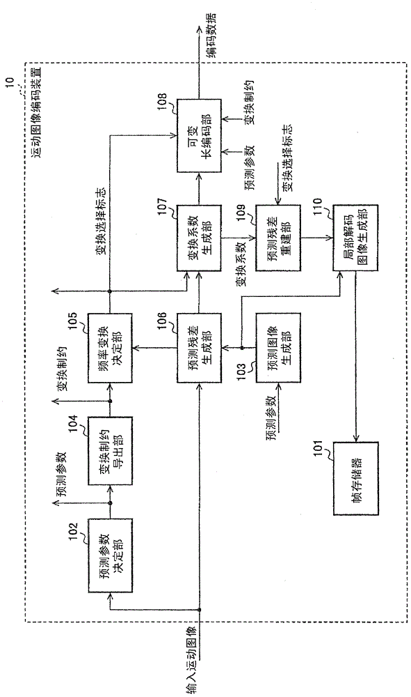
[0063] Below, refer to Figure 1 to Figure 11 A moving picture coding device 10 and a moving picture decoding device 20 which are one embodiment of the moving picture coding device and the moving picture decoding device of the present invention will be described. In addition, in the description of the drawings, the same reference numerals are assigned to the same elements, and description thereof will be omitted.

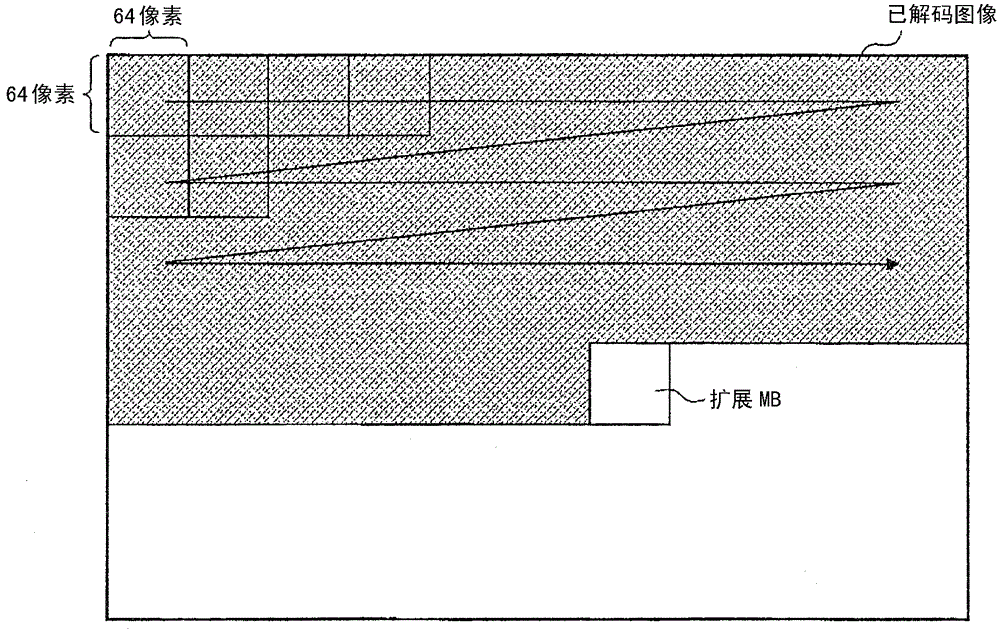
[0064] In the following description, it is assumed that an input video is sequentially input in units of extended MBs consisting of 64×64 pixels in the video encoding device to perform processing. Also, for the input order of extended MBs, assume figure 1 The raster scan order shown. However, the present invention can also be applied to cases where the size of the extended MB is other than the above. In particular, it is effective for an extended MB having a size larger than 16×16 pixels, which is a processing unit currently widely used.

[0065] The processing ...

Embodiment approach 2

[0236] Below, refer to Figure 12 to Figure 14 Next, a moving picture coding device 11 and a moving picture decoding device 21 as another embodiment of the moving picture coding device and the moving picture decoding device of the present invention will be described. In addition, in the description of the drawings, the same reference numerals are attached to the same elements to omit description.

[0237] The video encoding device 11 and the video decoding device 21 according to this embodiment are characterized in that the transformation constraint derivation unit 104 in the video encoding device 10 and the video decoding device 20 is replaced by the conversion candidate derivation unit 111 , thereby The conversion candidate list is directly derived without generating a conversion prohibition list.

[0238] In addition, the conversion constraint derivation unit 104 and the conversion candidate derivation unit 111 are collectively referred to as a conversion control derivatio...

Embodiment approach 3

[0289] Below, refer to Figure 15 ~ Figure 16 Next, a video encoding device 30 and a video decoding device 40 as another embodiment of the video encoding device and video decoding device of the present invention will be described. In addition, in the description of the drawings, the same reference numerals are assigned to the same elements, and description thereof will be omitted. In addition, the partition structure and transformation presets available in the video encoding device 30 and the video decoding device 40 are the same as those used in the video encoding device 11 and the video decoding device 21 .

[0290] The moving picture coding device 30 and the moving picture decoding device 40 in this embodiment are different from the moving picture coding device 11 and the moving picture decoding device 21 in that they have the following functions: use the scene (scene), frame, For a predetermined unit larger than an MB such as a slice, the method of deriving the conversion...


PUM


Abstract

While maintaining a high degree of freedom in choosing partition sizes and transformation sizes adapted for local characteristics of videos, the amount of metadata is decreased. A video encoding apparatus (10) divides an input video into blocks of a prescribed size and encodes the video block by block. The video encoding apparatus is provided with: a prediction parameter determining portion (102) that decides the block partition structure; a predictive image producing portion (103) that generates predictive images, partition by partition, as prescribed by the partition structure; a transform coefficient producing portion (107) which applies one of the frequency transformations included in a prescribed transformation preset to prediction residuals, i.e. the differences between predictive images and the input video; a transform restriction deriving portion (104) which generates the list of transform candidate, i.e. lists of frequency transformations that can be applied to each partition, on the basis of partition format information; and a variable-length-encoding portion (108) which, on the basis of the list of transform candidate and the transformation preset, performs variable-length encoding on transformation selection flags.

Description

technical field [0001] The present invention relates to a moving picture encoding device that encodes moving pictures to generate encoded data, and a moving picture decoding device that reproduces moving pictures based on transmitted and stored encoded data of moving pictures. Background technique [0002] <Introduction and Definition of Basic Terms> [0003] In the block-based video coding method, an input video to be coded is divided into predetermined processing units called macroblocks (hereinafter referred to as MB), and coding is performed for each MB to generate coded data. When reproducing a moving image, coded data to be decoded is processed and decoded in MB units to generate a decoded image. [0004] As a currently widespread block-based video coding method, there is a method specified in Non-Patent Document 1 (H.264 / AVC (Advanced Video Coding, Advanced Video Coding)). In H.264 / AVC, a prediction image estimated from an input video divided into MB units is ...

Claims


Application Information

Patent Timeline
Patent Type & Authority Patents(China)
IPC IPC(8): H04N19/176H04N19/119H04N19/122H04N19/61H04N19/109H04N19/12H04N19/463H04N19/157
CPCH04N19/109H04N19/119H04N19/12H04N19/122H04N19/157H04N19/176H04N19/463H04N19/61
Inventor 山本智幸猪饲知宏
Owner SHARP KK
Why Eureka
Try Eureka