
Tuning-fork type quartz-crystal vibrating pieces and quartz-crystal devices

A vibrating piece and tuning fork type technology, which is applied in the field of tuning fork type crystal vibrating piece and crystal device, can solve the problem of thickening and other problems, and achieve the effect of low CI value and small wiring impedance

Inactive Publication Date: 2012-03-21
NIHON DEMPA KOGYO CO LTD
View PDF8 Cites 3 Cited by
  • Summary
  • Abstract
  • Description
  • Claims
  • Application Information

AI Technical Summary

Problems solved by technology

[0003] However, in the tuning-fork type crystal vibrating piece of Patent Document 1, only the thickness of Au connecting the electrodes is thickened, and fine adjustment of flip-chip bonding that does not reach Cr as the texture is required.

Method used


Image

  • Tuning-fork type quartz-crystal vibrating pieces and quartz-crystal devices
  • Tuning-fork type quartz-crystal vibrating pieces and quartz-crystal devices
  • Tuning-fork type quartz-crystal vibrating pieces and quartz-crystal devices

Examples


no. 1 Embodiment approach

[0025]

[0026] Hereinafter, various embodiments of the present invention will be described with reference to the drawings.

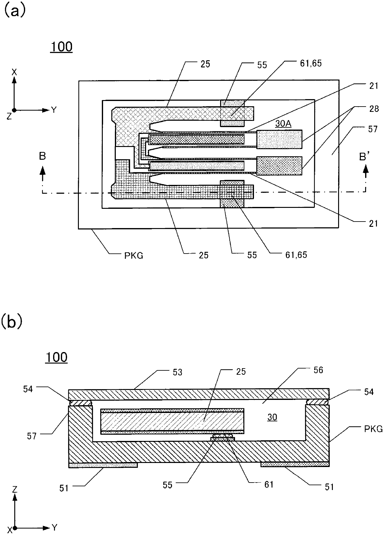
[0027] In the following embodiments, the extending direction of the vibrating arm is defined as the Y-axis direction, the arm width direction of the vibrating arm is defined as the X-axis direction, and the direction perpendicular to the X-axis and Y-axis direction is defined as the Z-axis direction.

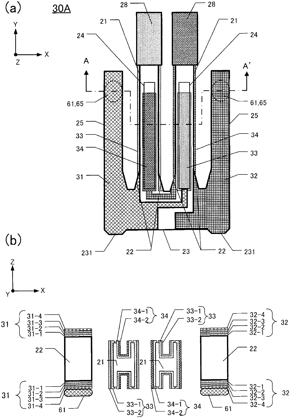
[0028] (Formation of the first tuning fork type crystal vibrating piece 30A)

[0029] figure 1 (a) is a plan view of the first tuning-fork type crystal vibrating piece 30A, figure 1 (b) is figure 1 (a) A-A' sectional view of the first tuning-fork type crystal vibrating piece 30A. The first tuning-fork-type crystal vibrating piece 30A has a pair of tuning-fork-shaped vibrating arms 21 and support arms 25 at the base 23 .

[0030] Such as figure 1 As shown in (a), the base portion 23 of the first tuning-fork type crystal vibrating piece 30A is genera...

no. 2 Embodiment approach

[0081]

[0082] Figure 6 (a) is a perspective view showing the structure of the second crystal device 110 of the present invention, Figure 6 (b) is in Figure 6 The C-C' section in (a) is a schematic cross-sectional view showing a state where the second crystal device 110 is separated. Figure 6 (a) is the figure which looked at the surface mount (SMD) type 2nd crystal device 110 from the cover 10 side.

[0083] Such as Figure 6 The second crystal device 110 shown in (a) consists of a crystal wafer made of a cover 10, a crystal lens made of a crystal frame 20 including a second tuning-fork type crystal vibrating piece 30B, and a crystal wafer made of a substrate 40. 3 layers to form the package 80 .

[0084] The substrate 40 has a first external electrode 45 and a second external electrode 46 on the bottom surface. The substrate 40 has a substrate-side concave portion 47 on one surface on the side of the crystal frame 20 . The substrate 40 has a through hole TH and ...


PUM


Abstract

Tuning-fork type quartz-crystal vibrating pieces are disclosed that exhibit low CI and low interconnection resistance. An exemplary vibrating piece (30A) includes vibrating arms (21) extending in a predetermined direction from a base, respective excitation electrodes (33, 34), a base (23) connected to the vibrating arms, respective supporting arms (25) disposed outboard of respective vibrating arms and extending from the base in the predetermined direction, and respective extraction electrodes (31, 32) connected to respective excitation electrodes. Each excitation electrode comprises two metal layers, including a first metal layer comprising at least one metal selected from Cr, Ni, Ti, Al and W, and a second metal layer overlying the first metal layer and comprising Au or Ag. Each extraction electrode comprises four metal layers, namely the first and second metal layers, a third metal layer overlying the second metal layer and comprising at least one metal selected from Cr, Ni, Ti, Al and W, and a fourth metal layer overlying the third metal layer and comprising Au or Ag.

Description

technical field [0001] The invention relates to a tuning fork type crystal vibrating piece and a crystal device with the tuning fork type crystal vibrating piece. In particular, it relates to a tuning-fork type crystal vibrating piece and a crystal device having a low CI (crystal impedance) value. Background technique [0002] Conventionally, a tuning-fork type crystal vibrating piece has used a laminated film made of Cr with Au formed thereon as an electrode film. The connection electrodes of the tuning-fork type crystal vibrating piece and the connection electrodes of the package are bonded using a conductive adhesive. In addition, the connection electrodes of the tuning-fork type crystal vibrating piece and the connection electrodes of the package are bonded by flip-chip bonding (ultrasonic bonding). The phenomenon that Cr of the connecting electrode of the tuning-fork crystal vibrating piece diffuses into Au or Au is sucked out by Cr causes the phenomenon that the conn...

Claims


Application Information

Patent Timeline
Patent Type & Authority Applications(China)
IPC IPC(8): H03H3/02H03H9/19
CPCH03H9/215H03H9/1035H03H9/131H03H9/0595H03H9/1021
Inventor 上野隼辅
Owner NIHON DEMPA KOGYO CO LTD
Learn More