Jack box for bus duct

A bus duct and plug-in box technology, applied in the field of bus duct plug-in boxes, can solve problems affecting installation work efficiency, unfavorable batch installation, and bus duct burnout, so as to improve product operation quality, eliminate loose fixation, and improve The effect of work efficiency

Inactive Publication Date: 2012-03-21
江苏金华厦电气有限公司
View PDF0 Cites 9 Cited by
  • Summary
  • Abstract
  • Description
  • Claims
  • Application Information

AI Technical Summary

Problems solved by technology

In many places, because the pins of the plug-in box and the busbar of the busway socket are not tightly inserted, the fixing of the plug-in box and the busway is not firm, and the vibration during the operation of the busway causes poor contact between the pins and the busway, resulting in the burning of the entire busway , and even burn out a large number of electrical equipment, causing serious economic losses and potential safety hazards
[0003] The locking device of the conventional plug-in box adopts ordinary bolts and nuts to be tightened up and down one by one. This method cannot determine whether the pins of the plug-in box and the busbar of the bus duct are inserted tightly, and whether the plug-in box and the bus duct are firmly fixed. It is difficult to guarantee the product running quality
[0004] When installing the product, due to the harsh installation environment and the skill level of the installation workers, it is easy to cause the bolts and nuts to not be tightened when installing a large number of plug-in boxes. The plug-in box and the bus duct are not firmly fixed. The busbar is loose, and the fixing bolts of the plug-in box are tightened one by one, which is not conducive to batch installation and affects the efficiency of installation

Method used


Image

  • Jack box for bus duct
  • Jack box for bus duct
  • Jack box for bus duct

Examples


Embodiment Construction

[0016] The present invention will be further described below in conjunction with accompanying drawing.

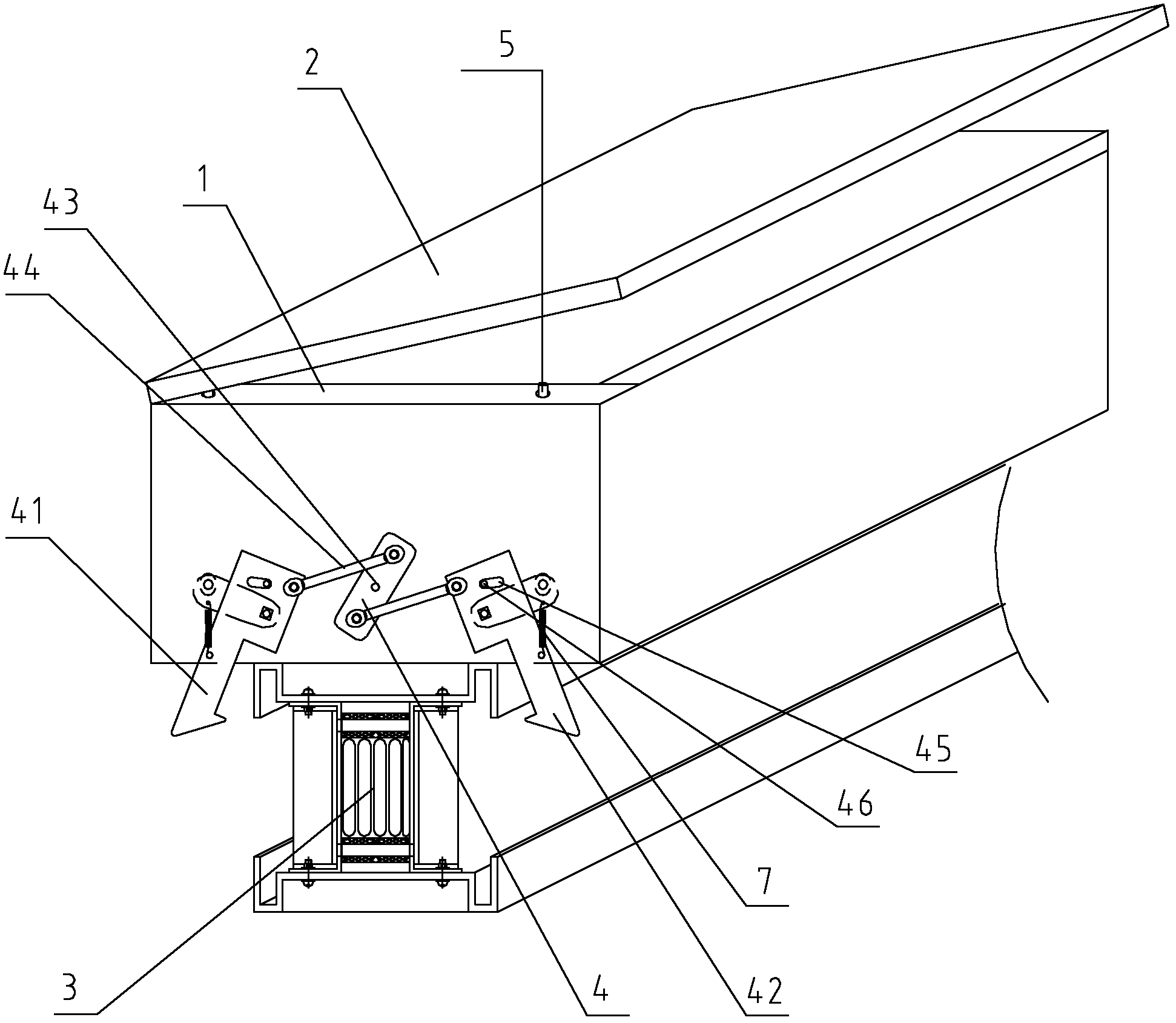
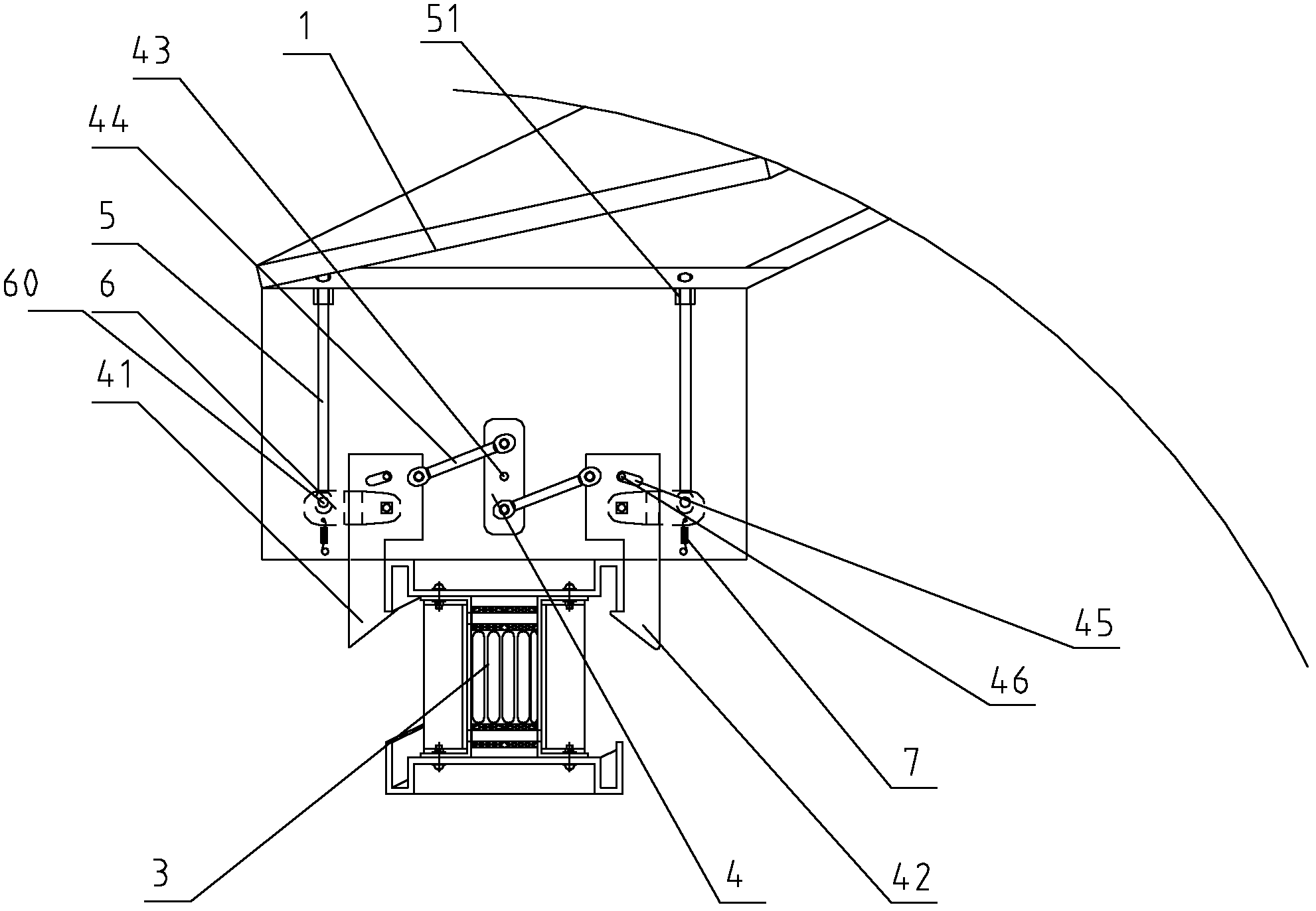
[0017] As shown in the figure, a plug-in box for bus duct includes a box body 1 of the plug-in box, a box cover 2 hinged to the upper edge of the box body 1, and two locks installed on the outside of the box body 1. The locking device 4 for tightening the bus duct 3, the locking device 4 includes a left locking hook 41 and a right locking hook 42, and the left and right locking hooks 41, 42 are arranged parallel and vertically on the outside of the box body 1 , one end of the left and right locking hooks 41, 42 extends below the box body 1; the left and right locking hooks 41, 42 are movably connected with the box body 1; the left and right locking hooks 41, 42 are installed on the box body 1 through the pin shaft, so that the left and right locking hooks 41, 42 can rotate on the box body 1; the box body 1 is provided with a return spring 7, and the return spring 7 is respe...


PUM


Abstract

The invention discloses a jack box for a bus duct. The jack box comprises a box body, a box cover, and locking devices mounted at two ends of the box body respectively. Each locking device comprises a left locking hook, a right locking hook, a linkage plate arranged between the left locking hook and the right locking hook, and offset springs, wherein the left locking hook, the right locking hook, and the linkage plate are parallel with one another and are vertically and movably arranged on the outer sides of the box body, one end of the left locking hook and one end of the right locking hook extend into the part below the box body, the upper end and the lower end of the linkage plate are movably connected with the upper ends of the left locking hook and the right locking hook respectively through linkage rods, the offset springs are arranged on the outer side surfaces of the left locking hook and the right locking hook, and two ends of the offset springs are fixedly connected with the box body and the corresponding left and right locking hooks. When the jack box is locked, the downward pressure for mounting the jack box leads the left locking hooks and the right locking hooks to open outwards, and after the jack box is jacked, the left locking hooks and the right locking hooks close inwards under the elasticity of the offset springs to hook a casing of the bus duct, so as to improve the use safety of the bus duct and ensure the running of the bus duct.

Description

technical field [0001] The invention relates to a plug-in box, in particular to a busway plug-in box, which belongs to the technical field of power transmission equipment. Background technique [0002] Low-voltage busway is an important product responsible for power transmission in the field of low-voltage power transmission and distribution. It has incomparable advantages for cables in high-current and industrial and mining sites. The most important and weakest link is the "plug-in unit". The key of the plug-in unit is the socket between the plug-in box and the busway body. In many places, because the pins of the plug-in box and the busbar of the busway socket are not tightly inserted, the fixing of the plug-in box and the busway is not firm, and the vibration during the operation of the busway causes poor contact between the pins and the busway, resulting in the burning of the entire busway , and even burn out a large number of electrical equipment, causing serious econom...

Claims


Application Information

Patent Timeline
Patent Type & Authority Applications(China)
IPC IPC(8): H02G5/00
CPCH02G5/08
Inventor 宋振达陈荣杨林钱文高中艳印赛虎
Owner 江苏金华厦电气有限公司
Why Eureka
Try Eureka