Non-combustible liquid-immersed transformer with adjustable liquid level pressure
A technology for transformers and pressure regulation, applied in the field of transformers, to achieve the effects of convenient layout, reduced design size, and improved insulation level
- Summary
- Abstract
- Description
- Claims
- Application Information
AI Technical Summary
Problems solved by technology
Method used
Image
Examples
Embodiment approach 1
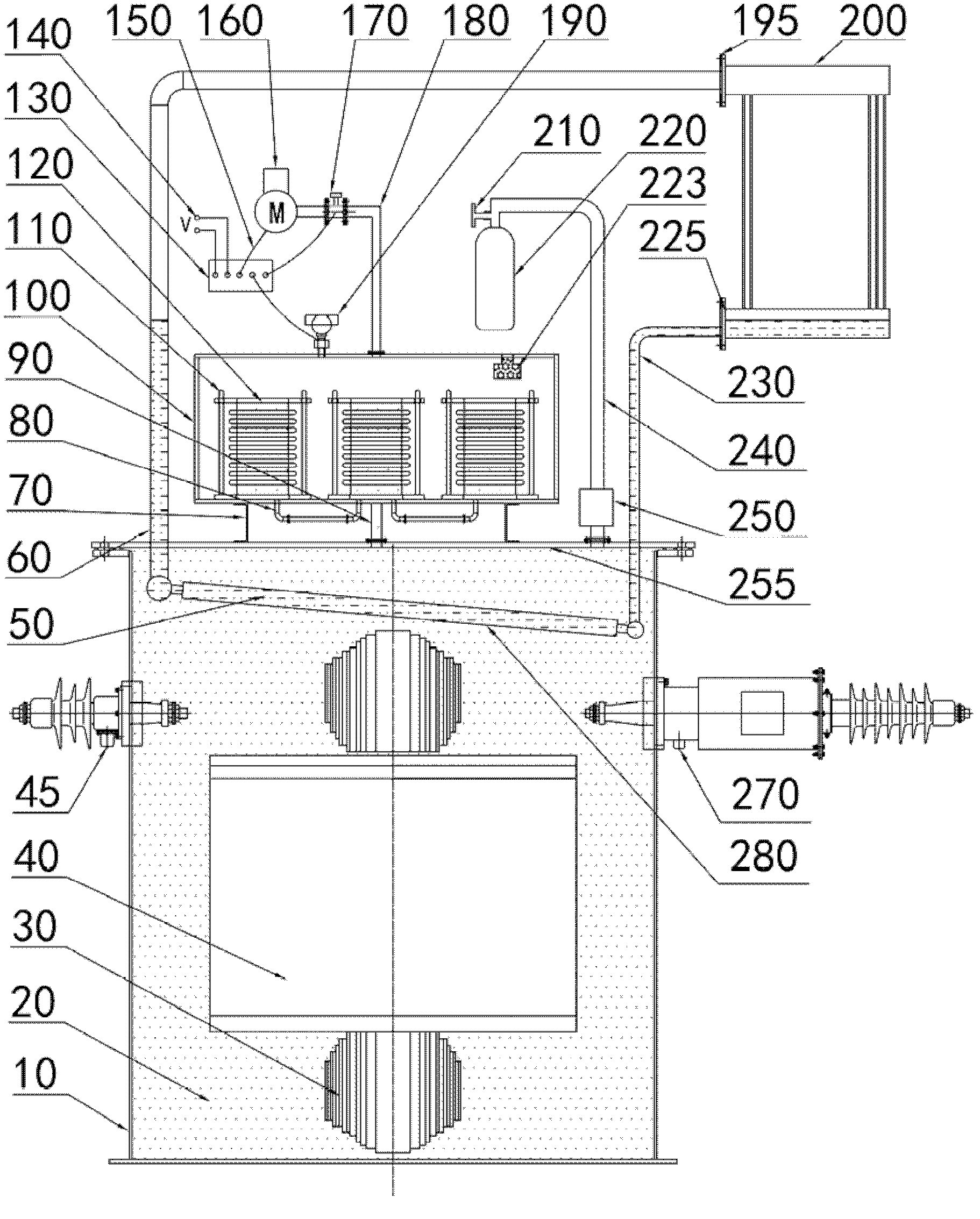
[0040] like figure 1 As shown, the specific embodiment of the present invention consists of a transformer oil tank 10, a non-combustible insulating liquid 20, an iron core 30, a coil 40, a low-voltage bushing 45, a high-voltage bushing 270, a liquid level pressure regulating system, a cooling system, and a sudden pressure treatment system composition. Among them, the liquid level pressure regulating system is located above the top cover 255 of the fuel tank, including a bracket 70, a communication pipeline 80, a communication pipeline 90, an air chamber 100, a guide rail 110, a metal bellows 120, an automatic air pressure controller 130, a power supply 140, Signal line 150, air pump 160, inflation valve 170, inflation pipeline 180, pressure sensor 190, moisture absorber 223; part of the cooling system is located in the transformer oil tank 10, and a part is located outside the transformer oil tank 10, including evaporating liquid 50, gas outlet pipeline 60, Cooler air inlet 1...
Embodiment approach 2
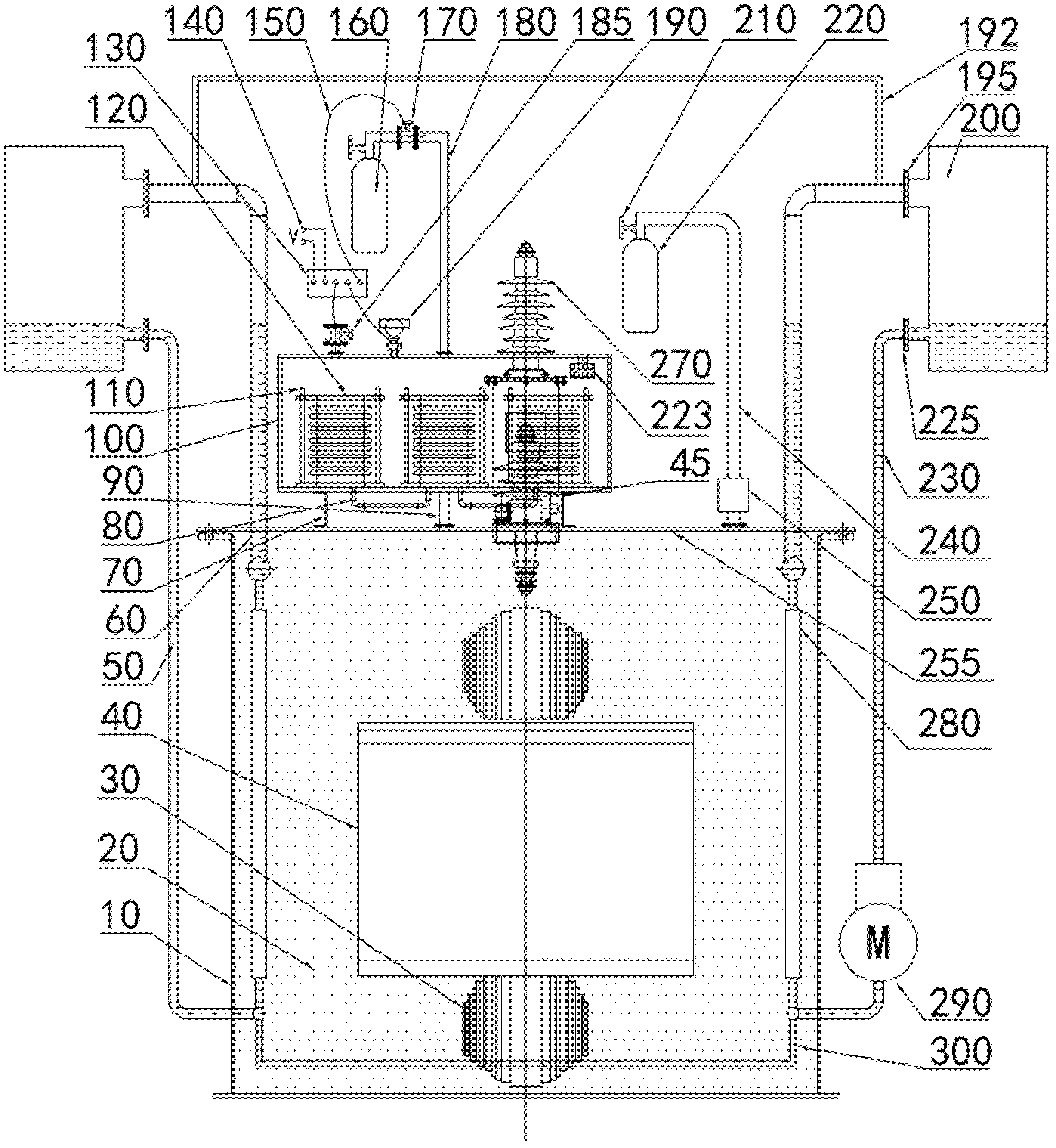
[0060] like figure 2 As shown, the second embodiment of the present invention consists of a transformer oil tank 10, a non-combustible insulating liquid 20, an iron core 30, a coil 40, a low-voltage bushing 45, a high-voltage bushing 270, a liquid level pressure regulating system, a cooling system, and a sudden pressure treatment system composition. Among them, the liquid level pressure regulating system is located above the top cover 255 of the fuel tank, including a bracket 70, a communication pipeline 80, a communication pipeline 90, an air chamber 100, a guide rail 110, a metal bellows 120, an automatic air pressure controller 130, a power supply 140, Signal line 150, air tank 160, inflation valve 170, inflation pipeline 180, deflation valve 185, pressure sensor 190, moisture absorber 223; part of the cooling system is located in the fuel tank 10, and the other part is outside the fuel tank 10, including evaporative liquid 50. Gas outlet pipeline 60, gas outlet communica...
Embodiment approach 3
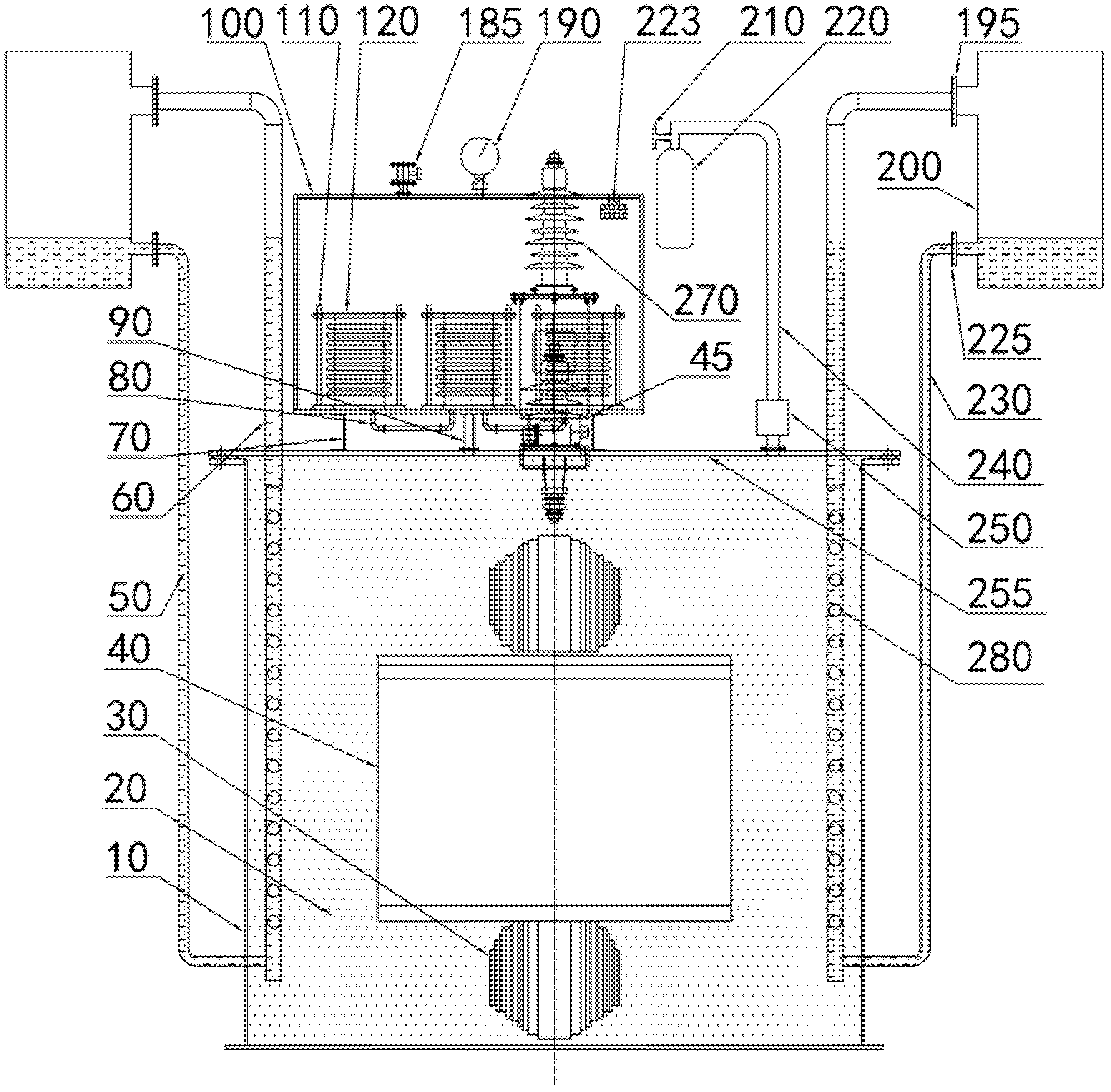
[0080] like image 3As shown, the third embodiment of the present invention consists of a transformer oil tank 10, a non-combustible insulating fluid 20, an iron core 30, a coil 40, a low-voltage bushing 45, a high-voltage bushing 270, a liquid level pressure regulating system, a cooling system, and a sudden pressure treatment system composition. Among them, the liquid level pressure regulating system is located above the top cover 255 of the fuel tank, including a bracket 70, a communication pipeline 80, a communication pipeline 90, an air chamber 100, a guide rail 110, a metal bellows 120, an inflation and discharge valve 185, and a pressure gauge 190 , moisture absorber 223; a part of the cooling system is located in the fuel tank 10, and the other part is outside the fuel tank 10, including the evaporating liquid 50, the gas outlet pipeline 60, the cooler air inlet 195, the cooler 200, the cooler liquid outlet 225, Liquid return pipeline 230 , rows of metal pipes 280 ; th...
PUM
 Abstract
Description
Claims
Application Information
 - R&D Engineer
- R&D Manager
- IP Professional
- Industry Leading Data Capabilities
- Powerful AI technology
- Patent DNA Extraction
Browse by: Latest US Patents, China's latest patents, Technical Efficacy Thesaurus, Application Domain, Technology Topic, Popular Technical Reports.
© 2024 PatSnap. All rights reserved.Legal|Privacy policy|Modern Slavery Act Transparency Statement|Sitemap|About US| Contact US: help@patsnap.com


