Asymmetrical-loading integral circular interpolation method of numerical control system
A technology of circular interpolation and numerical control system, which is applied in general control system, control/adjustment system, program control, etc., and can solve problems such as high hardware requirements, complex algorithms, and increased machine tool costs
- Summary
- Abstract
- Description
- Claims
- Application Information
AI Technical Summary
Problems solved by technology
Method used
Image
Examples
Embodiment 1
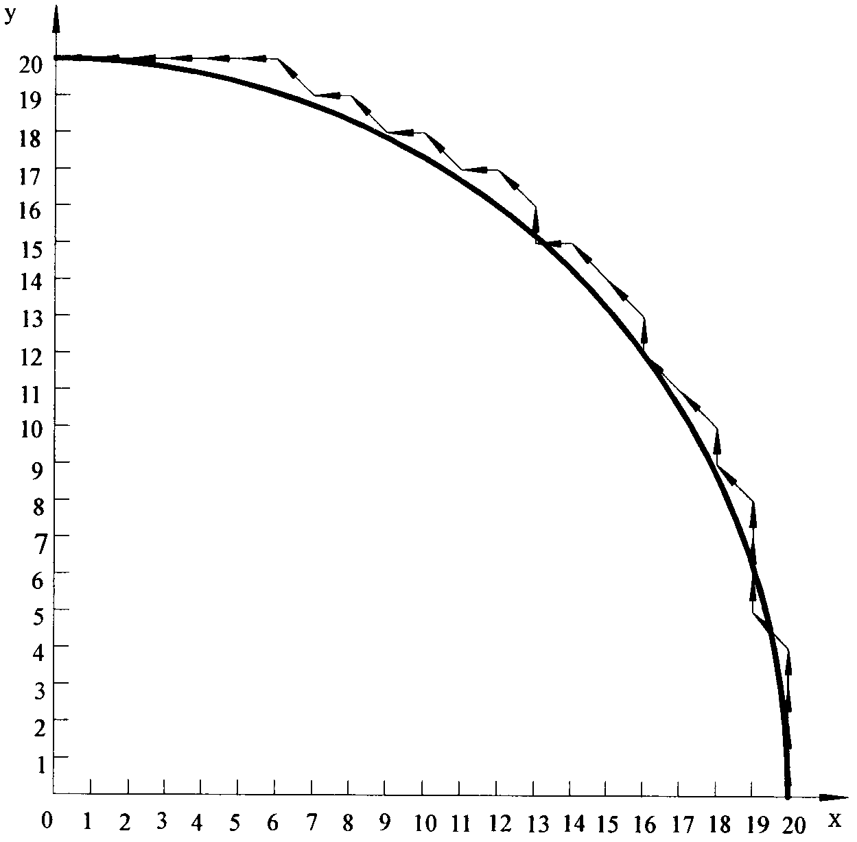
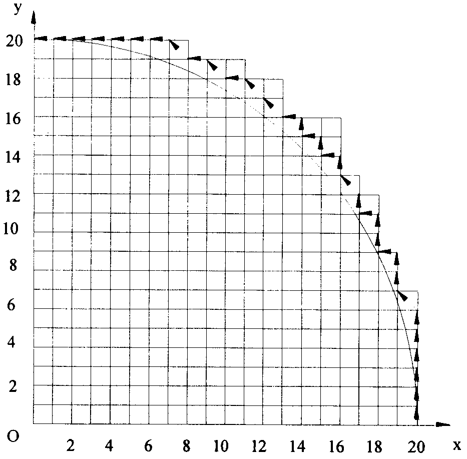
[0034] Interpolate the arc AB with the asymmetric loading integral arc interpolation method, the starting point coordinate of the arc AB is A(20,0), and the end point coordinate is B(0,20), then the proportional coefficient q=max( x 0 ,y 0 , x e ,y e )=max(20, 0, 0, 20)=20, its interpolation trajectory is as Image 6 As shown, the x-axis pulse distribution waveform is as Figure 7 As shown, the y-axis pulse distribution waveform is as Figure 8 shown.
[0035] The interpolation of the arc AB can be obtained by comparison, the interpolation times of the traditional integral circular interpolation method is 51 times; the interpolation times of the asymmetric loading integral circular interpolation method is 31 times. The number of imputations is reduced by 39.216%.
[0036] image 3 and Image 6 By comparison, it can be calculated that the maximum interpolation error of traditional integral circular interpolation is The maximum interpolation error of the asymmetric lo...
Embodiment 2
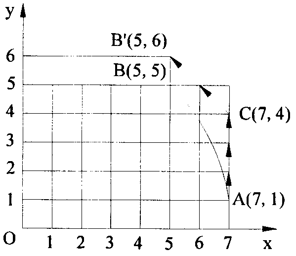
[0043] Use the asymmetric loading integral circular interpolation method to interpolate circular arc AB. The starting point coordinates of circular arc AB are A(7,1), and the end point coordinates are B(5,5), so the number of pulses is q= max(x 0 ,y 0 , x e ,y e )=max(7,1,5,5)=7, its interpolation trajectory is as Figure 12 shown. The interpolation of the arc AB can be concluded by comparison that the interpolation times of the traditional integral circular interpolation method is 6 times; the interpolation times of the asymmetric loading integral circular interpolation method is 4 times, and the interpolation times A reduction of 33.333%. and figure 1 In comparison, after the interpolation ends, the actual tool position just falls on the end point coordinate B(5, 5). The x-axis pulse distribution waveform is as Figure 13 shown, with Figure 10 In comparison, the maximum pulse interval is reduced from 5 to 2. The y-axis pulse distribution waveform is as Figure 14...
PUM
 Abstract
Description
Claims
Application Information
 - Generate Ideas
- Intellectual Property
- Life Sciences
- Materials
- Tech Scout
- Unparalleled Data Quality
- Higher Quality Content
- 60% Fewer Hallucinations
Browse by: Latest US Patents, China's latest patents, Technical Efficacy Thesaurus, Application Domain, Technology Topic, Popular Technical Reports.
© 2025 PatSnap. All rights reserved.Legal|Privacy policy|Modern Slavery Act Transparency Statement|Sitemap|About US| Contact US: help@patsnap.com


