Contact pin assembly of optical fiber connector

An optical fiber connector and pin technology, applied in the field of optical fiber connector pin assemblies, can solve the problems of low assembly efficiency of optical fiber connectors, and achieve the effect of solving low assembly efficiency

Inactive Publication Date: 2012-03-21
CHINA AVIATION OPTICAL-ELECTRICAL TECH CO LTD
View PDF8 Cites 2 Cited by
  • Summary
  • Abstract
  • Description
  • Claims
  • Application Information

AI Technical Summary

Problems solved by technology

[0003] The purpose of the present invention is to provide a fiber optic connector ferrule assembly to solve the problem of low assembly efficiency of fiber optic connectors during manufacture

Method used


Image

  • Contact pin assembly of optical fiber connector
  • Contact pin assembly of optical fiber connector
  • Contact pin assembly of optical fiber connector

Examples


Embodiment Construction

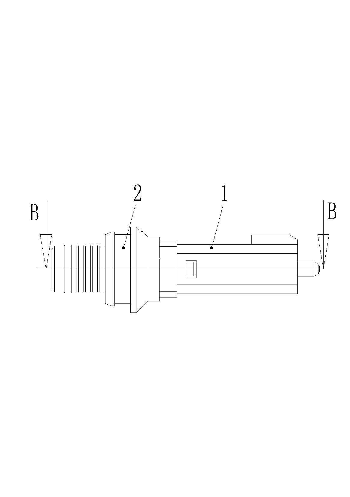
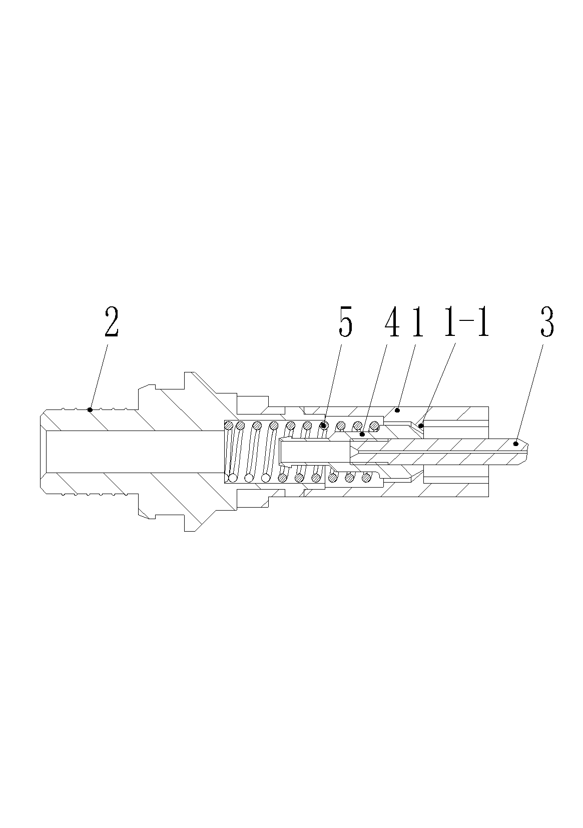
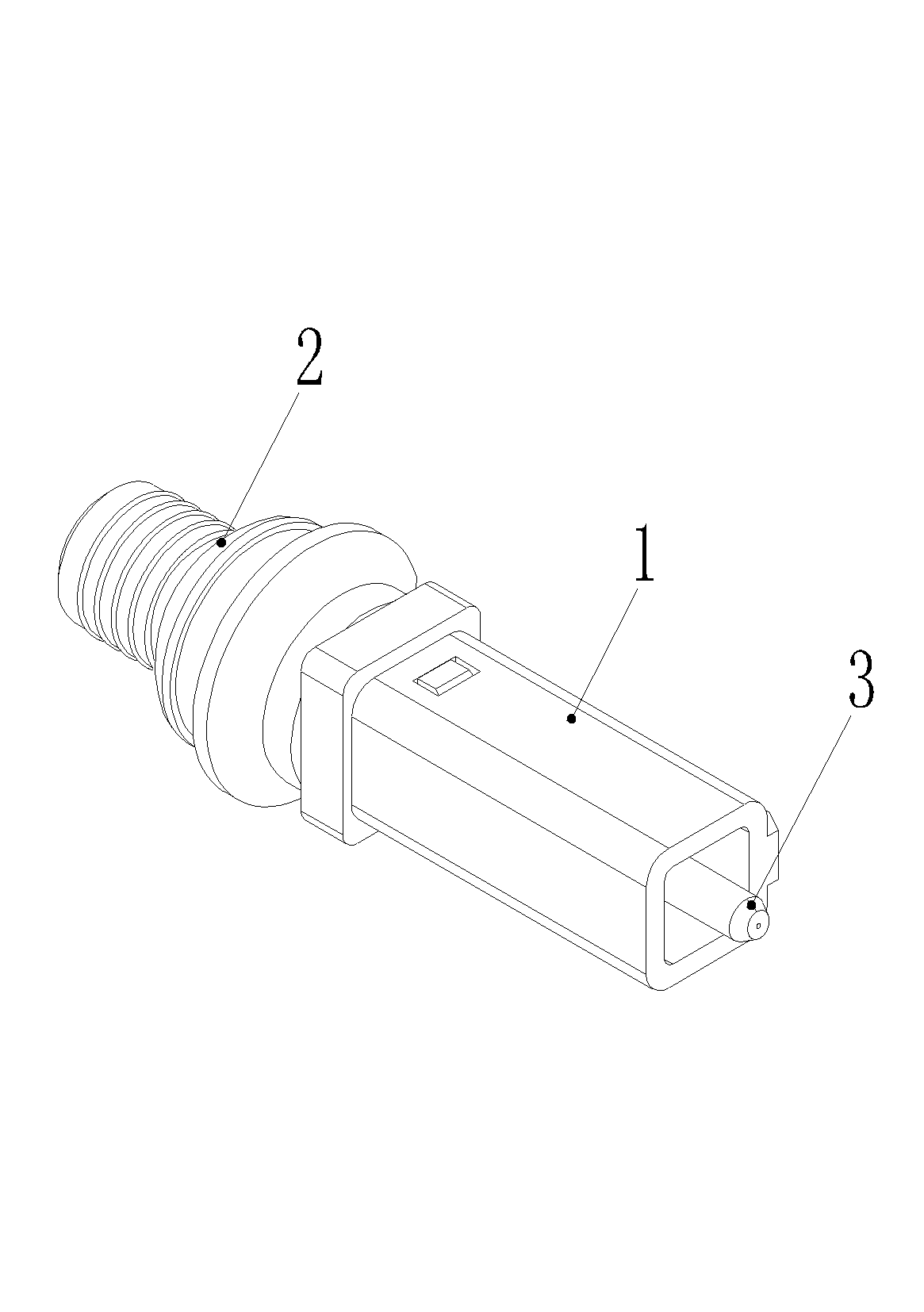
[0015] Embodiment 1 of an optical fiber connector ferrule assembly, such as Figure 1-5 As shown, there is a front housing 1 and a rear housing 2. The outer contour of the front housing 1 is rectangular and has an inner hole extending axially. A baffle plate 1-1 is arranged in the inner hole of the front housing 1. The plate 1-1 has a through hole through the front and back, and the pin 3 is installed in the through hole along the axial movable guide. The rear side of -1 is limited in position, and its rear end is provided with a buffer spring 5; the front housing 1 is provided with a front housing hanging hole 1-2 on its circumference, that is, a through hole located on the circumference of the front housing The front end of the rear housing 2 is provided with elastic wedges 2-1 which can be elastically deformed in the radial direction. After the front end of the rear housing 2 is inserted into the rear end of the front housing 1, each elastic wedge is embedded In the front ...


PUM


Abstract

The invention relates to a contact pin assembly of an optical fiber connector, comprising a contact pin shell formed by a front shell and a rear shell. An annular groove is coaxially arranged on the outer wall surface of the rear shell, and a convex ring on the inner wall surface of a corresponding protective shell can be embedded in the annular groove; and fitting surfaces which are in interference fit with the convex ring on the inner wall surface of the corresponding protective shell are arranged on the front and rear groove walls and/or the bottom of the annular groove. As the annular groove is arranged on the rear shell of the contact pin assembly of the optical fiber connector, and the fitting surfaces which are in interference fit with the convex ring on the inner wall surface of the corresponding protective shell are arranged on the front and rear groove walls and/or the bottom of the annular groove, in assembly, only the contact pin component needs to be assembled in the corresponding protective shell forcibly so as to fix the contact pin assembly with an inner shell, and to avoid the processing steps of rubber filling, pressing mounting and the like of a traditional optical fiber connector, thereby solving the problem of low assembly efficiency during the manufacturing of the optical fiber connector.

Description

technical field [0001] The invention relates to an optical cable connection device, in particular to an optical fiber connector pin assembly. Background technique [0002] Compared with traditional connection methods such as fusion splicing, cold splicing or on-site grinding splicing of the traditional optical fiber terminal, the pre-connection technology adopts the optical fiber straight-through method, that is, the optical fiber has no connection point. According to the requirements of customers, the products are customized by the factory, and the grinding process is carried out according to the standard procedure. All technical indicators comply with IEC, TIA and related standards. In this regard, the technical indicators far exceed the connectors ground on site. Among them, the optical fiber connector is an indispensable key component in the pre-connection technology. The general optical fiber connector includes a pin assembly, and the pin assembly includes a rectangular...

Claims


Application Information

Patent Timeline
Patent Type & Authority Applications(China)
IPC IPC(8): G02B6/38
Inventor 李小卫李卫可
Owner CHINA AVIATION OPTICAL-ELECTRICAL TECH CO LTD
Why Eureka
Try Eureka