Fan and manufacture method thereof

A fan and metal shell technology, applied in the thin fan and its manufacturing field, can solve the problems of unfavorable embossing groove 131 processing, complex mold design, unfavorable demand for impeller thinning, etc.

Active Publication Date: 2012-03-21
DELTA ELECTRONICS INC
View PDF7 Cites 13 Cited by
  • Summary
  • Abstract
  • Description
  • Claims
  • Application Information

AI Technical Summary

Problems solved by technology

[0004] However, the existing impeller structure has the following disadvantages: because the hub 10 has a minimum thickness limit, and the hub 10 is provided with structures such as the shaft-setting convex ring 101 and the reinforcing rib 102, the mold design is more complicated, which is not conducive to the thinning of the impeller.
Furthermore, since the top of the rotating shaft 13 has to add embossed grooves 131 to strengthen the bonding strength between the rotating shaft 13 and the hub 10, under the requirement of thinning the impeller, the smaller size of the rotating shaft 13 is not conducive to the processing of the embossed grooves 131

Method used


Image

  • Fan and manufacture method thereof
  • Fan and manufacture method thereof
  • Fan and manufacture method thereof

Examples


Embodiment Construction

[0032] Some typical embodiments embodying the features and advantages of the present invention will be described in detail in the description in the following paragraphs. It should be understood that the present invention can have various changes in different aspects, all of which do not depart from the scope of the present invention, and the description and drawings therein are used as illustrations in nature, not to limit the present invention .

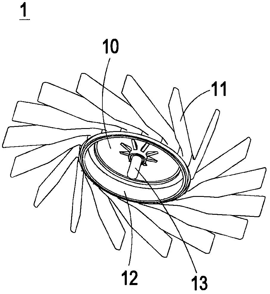
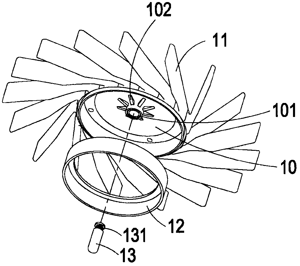
[0033] see Figure 2A to Figure 2C ,in Figure 2A It is a schematic diagram of the structure of the impeller in a preferred embodiment of the present invention, Figure 2B for Figure 2A exploded view, Figure 2C for Figure 2A cutaway view. As shown in the figure, the impeller 2 includes a hub 20 , a plurality of blades 21 , a metal shell 22 and a shaft 23 . Wherein, the hub 20 is sheathed on the metal shell 22 , the blade 21 is arranged around the periphery of the hub 20 , and the blade 21 and the hub 20 are integrally for...


PUM

PropertyMeasurementUnit
thicknessaaaaaaaaaa

Abstract

The invention discloses a fan and a manufacture method thereof. The thinned fan comprises a motor base, a bearing, an impeller, a stator and a magnetic element, wherein the center of the motor base is provided with a bearing seat, the bearing is accommodated in the bearing seat; the impeller comprises a metal housing, a hub, a plurality of blades and a rotating shaft; the metal housing is provided with a top wall and a circumferential wall extending from the peripheral edge of the top wall axially; the hub is sleeved on the metal housing, the impeller is annularly arranged on the periphery of the hub, the rotating shaft is convexly arranged on the center of the top wall of the metal housing and penetrates in the bearing, wherein the top wall of the metal housing is not provided with a convex ring for placing a shaft, and the rotating shaft is directly combined with the top wall of the metal housing in a laser welding manner; and the stator is sleeved on the outer peripheral edge of the bearing seat, and the magnetic element is arranged on the inner edge of the metal housing and arranged corresponding to the stator. The invention also discloses a manufacture method of the fan.

Description

technical field [0001] The invention relates to a fan and its manufacturing method, in particular to a thin fan and its manufacturing method. Background technique [0002] The heat dissipation fan is an indispensable and important device in various electronic equipment. With its heat dissipation function, it can prevent the electronic equipment from overheating and achieve the function of maintaining the normal operation of the electronic equipment. see Figure 1A to Figure 1C ,in Figure 1A It is a structural schematic diagram of an impeller of an existing fan, Figure 1B for Figure 1A exploded view of , and Figure 1C for Figure 1A cutaway view. As shown in the figure, the impeller 1 includes a hub 10, a plurality of blades 11, a metal ring 12 and a rotating shaft 13, wherein the blade 11 ring is arranged on the periphery of the hub 10, and the blades 11 and the hub 10 are integrally formed with plastic, and the metal ring 12 is disposed on the inner edge of the hu...

Claims


Application Information

Patent Timeline
Patent Type & Authority Applications(China)
IPC IPC(8): F04D25/08F04D29/52F04D29/32F04D29/053B23K26/00B23K26/21
Inventor 陈秋恭王君智王兵峰
Owner DELTA ELECTRONICS INC
Why Eureka
Try Eureka