Truss imitating type damper structure transfer layer

A technology for structural transfer floors and dampers, which is applied to building components, earthquake resistance, etc., can solve problems such as insufficient earthquake resistance, achieve simple construction, reduce bending moment and shear force, and reduce interstory displacement and interstory shear force Effect

Inactive Publication Date: 2012-03-21
CHIAN JIANGXI CORP FOR INT ECONOMIC & TECHN COOPERATION
View PDF5 Cites 7 Cited by
  • Summary
  • Abstract
  • Description
  • Claims
  • Application Information

AI Technical Summary

Problems solved by technology

[0006] The technical problem to be solved by the present invention is to provide a new structural form of the transfer layer in order to solve the problem of insufficient seismic capacity of the structure with the transfer layer

Method used


Image

  • Truss imitating type damper structure transfer layer
  • Truss imitating type damper structure transfer layer
  • Truss imitating type damper structure transfer layer

Examples


Embodiment 1

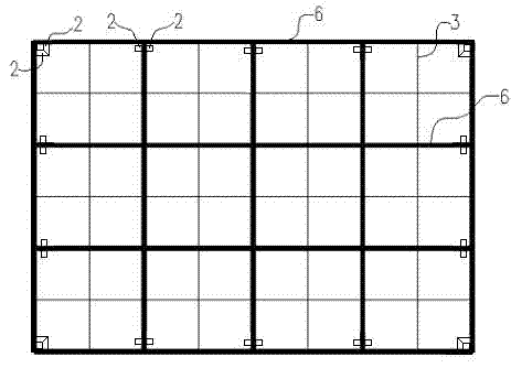
[0023] Example 1: The transfer layer of the truss-like damper structure is composed of the frame column 5 of the two main facades, the transfer beam 4, the floor beam 6 and the damper 1 to form the transfer layer of the truss-like damper structure; the transfer beam 4 supports the seismic wall 7 The upper building structure, the transfer beam 4 and the floor beam 6 are provided with corresponding secondary beams 3; the support 2 is installed under the secondary beam 3 of the beam system surrounding the beam system close to the transfer beam 4, and the beam of the floor beam 6 The support 2 is also installed on the beam system of the floor beam 6, and the support 2 above the beam system of the floor beam 6 is installed on the secondary beam 3 or the floor beam 6 to ensure that when the damper 1 is installed on the support 2 above the beam system of the floor beam 6 It corresponds to the lower support 2 of the secondary beam 3 of the beam system of the conversion beam 4 . The ...

Embodiment 2

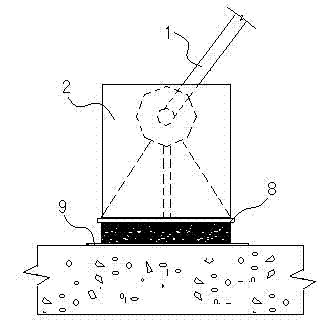
[0024] Example 2: The structure of the truss-type transfer layer imitating the truss-type damper structure, the structure of the truss-type transfer layer formed by the frame column 5, the transfer beam 4, the floor beam 6 and the damper 1 is the same as that of the first embodiment. Backing plate 9 adopts 20mm cast steel plate. Damper 1 adopts hydraulic damper. Soft base pad 8 adopts plastic pad. The installation angle α between the central axis of the damper 1 and the horizontal center line of the transfer beam 4 or the floor beam 6 is 55°.

[0025] The invention is mainly used for the seismic design research, conceptual design and actual engineering design of the structure with the transfer layer in the building, and is mainly composed of a viscoelastic damper and a laminated rubber bearing, wherein: the viscoelastic damper is in the beam system of the transfer beam In the range of the two main facades, the transfer beams on the four sides of the structure are arranged ...


PUM


Abstract

The invention discloses a truss imitating type damper structure transfer layer, which is a truss type combination structure formed by a frame column, a transferring beam, a floor beam and damper. Upper portion structures of shear walls and the like are constructed on the transferring beam, stagger beam bodies form a beam system of the transferring beam, and stagger beam bodies form a beam system of the floor beam. The beam system of the transferring beam and the beam system of the floor beam are respectively provided with secondary beams. The secondary beams are provided with supports, a support under the beam system of the transferring beam and a support above the beam system of the floor beam are connected through a damper which is installed in inclined mode, and soft base cushions and cushion boards are sequentially installed between the supports and the secondary beams. The truss imitating type damper structure transfer layer breaks through a quake-proof design and research method, and a mixed damping device is composed of the damper, the soft base cushions and the supports, thereby reducing earthquake influence of a transfer layer structure. The truss imitating type damper structure transfer layer is simple in structure, economical and practical and has great popularization value.

Description

technical field [0001] The invention relates to the field of civil engineering construction, and belongs to an anti-seismic structure form with a transfer layer structure in building construction, in particular to a transfer layer of a structure imitating a truss type damper. Background technique [0002] Since scholars in the former Soviet Union and Eastern Europe first proposed the design concept of structures with transfer floors in the 1950s and 1960s, many high-rise buildings with transfer floors have been built around the world. At present, the commonly used transfer forms mainly include the following types: beam transfer structure, thick plate transfer structure, box transfer structure, and truss transfer structure. [0003] In recent years, a large number of high-rise buildings with transfer floors have been built at home and abroad, and in-depth research has been done on beam-type high-rise buildings with transfer floors. Research on seismic performance [J]. World ...

Claims


Application Information

Patent Timeline
Patent Type & Authority Applications(China)
IPC IPC(8): E04B1/98
Inventor 李宗根徐家云王琦龚文凯胡绍辉高丽媛
Owner CHIAN JIANGXI CORP FOR INT ECONOMIC & TECHN COOPERATION
Why Eureka
Try Eureka