
Electric soldering iron

An electric soldering iron and heating core technology, applied in soldering irons, metal processing equipment, manufacturing tools, etc., can solve the problems of burnt components and losses, and achieve the effect of convenient welding and overall beautiful appearance.

Inactive Publication Date: 2012-03-21
龚晓建
View PDF0 Cites 1 Cited by
  • Summary
  • Abstract
  • Description
  • Claims
  • Application Information

AI Technical Summary

Problems solved by technology

That is, use a soldering iron to take a little soldering wire and point it on the line joint that needs to be soldered. Since the soldering iron is stable, the soldering wire will melt as soon as it touches the soldering wire. Therefore, the melted soldering wire is easy to drip onto the components during welding and cause burns. components, causing serious damage to

Method used


Image

  • Electric soldering iron
  • Electric soldering iron

Examples


Embodiment Construction

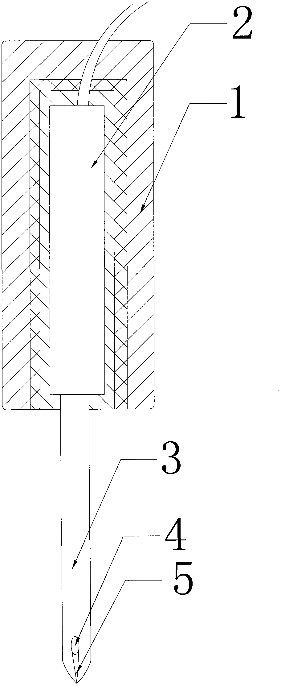
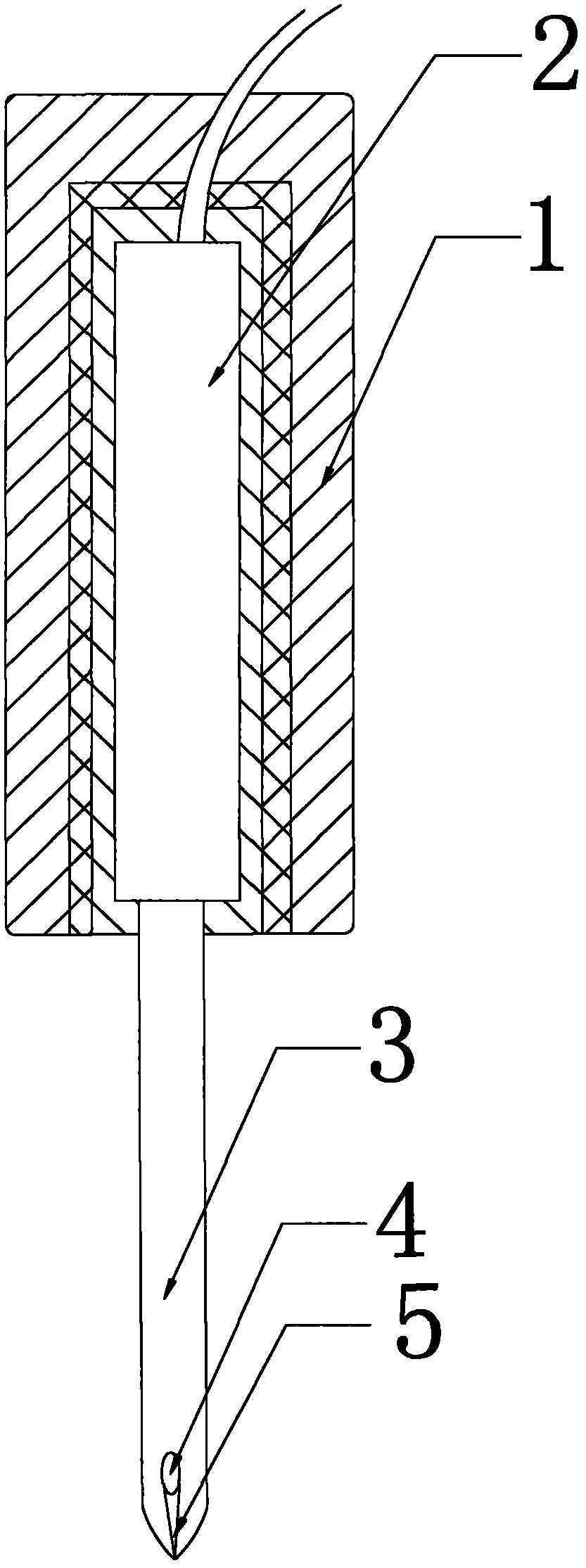
[0010] Such as figure 1 As shown, the electric soldering iron includes a handle 1, a heating core 2 and a welding head 3. The heating core 2 is placed in the handle 1, and the heating core 2 is in contact with the welding head 3. The lower part of the welding head 3 has a semi-conical structure. There is a groove 4 on the bottom of the groove 4, and a flow channel 5 is also opened below the groove 4. One end of the flow channel 5 communicates with the groove 4, and the other end leads to the lower end of the welding head 3, so that when welding Put the electric soldering iron horizontally, place the groove 4 facing upwards, place the welding wire in the groove 4, and after the welding wire melts, move the horizontal welding head of the electric soldering iron to the joint of the circuit, and gently lift the handle 1 so that The molten welding wire drips on the joint of the line to achieve the purpose of welding. This not only ensures that the molten welding wire will not drip...


PUM


Abstract

The invention relates to an electric soldering iron, comprising a handle, a heating core and a welding head, wherein the heating core is arranged in the handle and is in contact with the welding head, and the lower part of the welding head is of a semi-conical structure. The electric soldering iron is characterized in that a groove is formed in the lower part of the welding head, a flow channel is formed below the groove, one end of the flow channel is communicated with the groove, and the other end of the flow channel is communicated all through to a tail end at the lower part of the welding head. The electric soldering iron provided by the invention has the advantages of convenience for welding, safety and reliability, and a welded circuit joint has an attractive overall appearance.

Description

technical field [0001] The invention relates to an electric soldering iron. Background technique [0002] When the existing electric soldering iron is welding the circuit, it is necessary to complete the welding process while melting the welding wire. That is, use a soldering iron to take a little soldering wire and point it on the line joint that needs to be soldered. Since the soldering iron is stable, the soldering wire will melt as soon as it touches the soldering wire. Therefore, the melted soldering wire is easy to drip onto the components during welding and cause burns. Components, causing serious losses. Contents of the invention [0003] The object of the present invention is to provide an electric soldering iron which can accurately drop molten welding wire on the joint of the circuit. [0004] The technical scheme adopted in the present invention is: [0005] An electric soldering iron includes a handle, a heating core and a welding head, the heating core is ...

Claims


Application Information

Patent Timeline
IPC IPC(8): B23K3/03
Inventor 龚晓建
Owner 龚晓建
Learn More