
Fishing reel

A wire reel and magnet technology, applied in fishing reels, fishing, applications, etc., can solve the problems of reduced rotation performance of the drive shaft, reduced rotation performance, corrosion of ball bearings, etc., to achieve space saving and suppression of scattering range Effect

Active Publication Date: 2012-03-21
DAIWA SEIKO CORPORATION
View PDF6 Cites 23 Cited by
  • Summary
  • Abstract
  • Description
  • Claims
  • Application Information

AI Technical Summary

Problems solved by technology

[0003] However, when a fishing reel is used in an actual fishing ground, there will be a unique problem that seawater, sand, foreign matter, etc. tend to adhere to the reel body. intrusion into the ball bearings supporting the drive shaft
In addition, if sea water, sand, foreign matter, etc. adhere to or invade the ball bearing, the ball bearing will be corroded, etc., resulting in a decrease in its rotational performance.
[0004] As a solution to this problem, it is generally done to make a sealing member made of an elastic material contact the outer periphery of the drive shaft close to the ball bearing, thereby realizing waterproof and dustproof of the ball bearing, but the following problems have been pointed out: The influence of the contact pressure of the sealing member made of elastic material reduces the rotation performance of the drive shaft

Method used


Image

  • Fishing reel
  • Fishing reel
  • Fishing reel

Examples


Embodiment Construction

[0068] Hereinafter, embodiments of the fishing reel according to the present invention will be described with reference to the drawings.

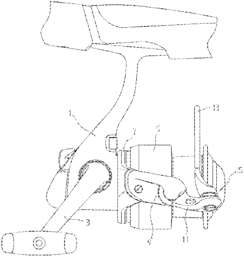
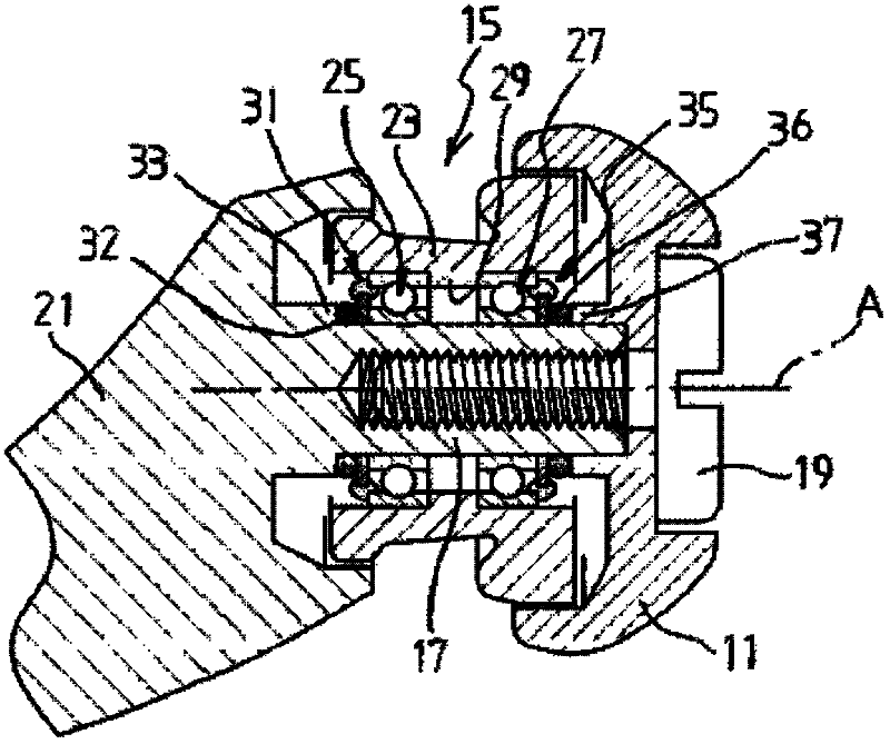
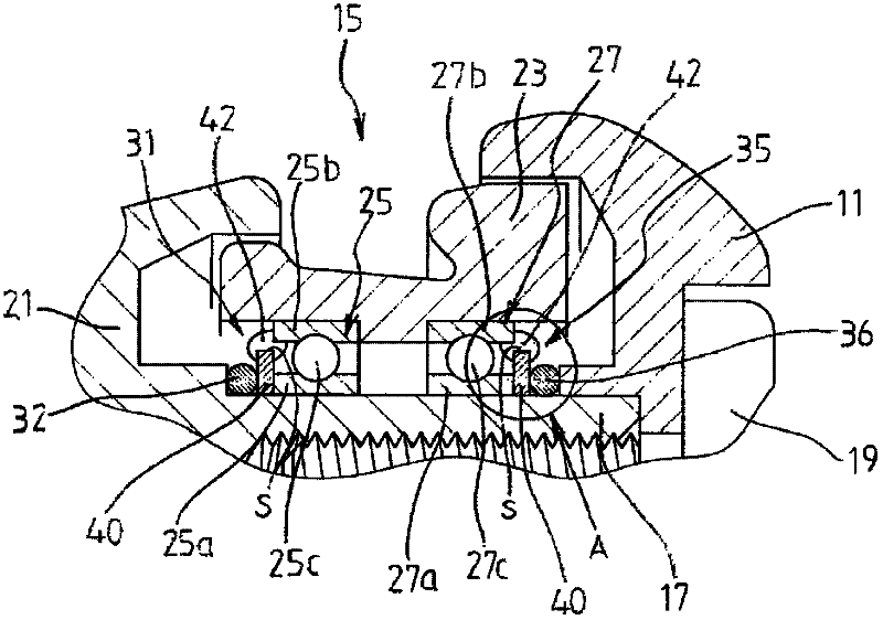
[0069] Figure 1 ~ Figure 4 The first embodiment of the present invention is shown. like figure 1 As shown, the fishing reel according to this embodiment is a spinning type reel and has a reel body 1 . Inside the cord reel body 1 is provided a drive gear (not shown) that is rotationally driven by rotating the handle 3, and a pinion gear (not shown, drive shaft) meshes with the drive gear. Inside the pinion, a spool shaft (not shown) passes in the axial direction, and at the tip end of the spool shaft, the spool 5 on which the fishing line is wound is mounted so as to be rotatable. At this time, the spool shaft (spool) is configured to move forward and backward by the rotation of the drive gear through a swing mechanism (not shown) engaged with the drive gear.

[0070] Furthermore, a rotor 7 that rotates integrally with the pinion is pro...


PUM


Abstract

The invention provides a fishing reel having a light-weight, compact and easy-to-assemble magnetic seal mechanism which allows greater freedom in material selection of the rotating member. A fishing reel according to one embodiment comprises a rotating body rotatably supported via a ball bearing and a magnetic seal mechanism for sealing the ball bearing. The magnetic seal mechanism comprises a magnet disposed in parallel with either a magnetic inner or outer ring of the ball bearing, and magnetic fluid disposed between the magnet and said inner or outer ring, magnetic fluid being retained by a magnetic circuit formed therebetween to seal space defined between the magnet and said inner or outer ring. The present invention further includes a receiver for receiving scattered portions of the magnetic fluid, wherein the receiver is disposed along a direction to which the magnetic fluid may fly off due to a centrifugal force within a range where a magnetic force of the magnet can act.

Description

technical field [0001] The present invention relates to a fishing reel characterized by a sealing mechanism that seals a support structure that rotatably supports a rotating body. Background technique [0002] Generally, a fishing line reel is configured such that a fishing line is wound around a spool through a power transmission mechanism by a rotational operation of a handle. The power transmission mechanism is provided with a drive shaft that is driven to rotate as the handle is rotated. Generally, the drive shaft is rotatably supported by ball bearings (bearings) provided on the cord reel body. [0003] However, when a fishing reel is used in an actual fishing ground, there will be a unique problem that seawater, sand, foreign matter, etc. tend to adhere to the reel body. Intrusion into the ball bearings supporting the drive shaft. Furthermore, if seawater, sand, foreign matter, etc. adhere to or penetrate into the ball bearing, the ball bearing will be corroded, etc....

Claims


Application Information

Patent Timeline
IPC IPC(8): A01K89/01
CPCA01K89/01A01K89/0108A01K89/0111A01K89/015A01K89/011221A01K89/011223
Inventor 小原武惠藤冈真嗣
Owner DAIWA SEIKO CORPORATION
Learn More