
Power supply resetting circuit

A power reset and power voltage technology, applied in the direction of measuring current/voltage, measuring devices, electrical components, etc., can solve problems such as failure to work normally, internal signal disorder of the system, and voltage cannot drop in real time, so as to avoid misoperation.

Inactive Publication Date: 2012-03-14
HOLTEK SEMICON
View PDF4 Cites 21 Cited by
  • Summary
  • Abstract
  • Description
  • Claims
  • Application Information

AI Technical Summary

Problems solved by technology

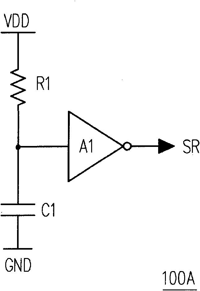
[0005] However if Figure 2B As shown, if the discharge speed on the capacitor C1 is too slow, the voltage on the capacitor C1 cannot drop to the conversion level of the inverter A1 in real time, and the inverter A1 cannot output a reset at its output terminal. Signal SR, and then cause the system to be in an unpredictable state because the power supply voltage VDD is too low
When the power supply voltage VDD returns to the normal working voltage, the system will not work properly due to internal signal disorder

Method used


Image

  • Power supply resetting circuit
  • Power supply resetting circuit
  • Power supply resetting circuit

Examples


Embodiment Construction

[0048] image 3 It is a schematic diagram of a power reset circuit according to an embodiment of the present invention. Please refer to image 3 , wherein the power reset circuit 300 is built in a system (not shown), the power reset circuit 300 includes a power reset unit 302 , a voltage detection unit 304 , and a switch unit 306 . Wherein the switch unit 306 is coupled between the voltage detection unit 304 and the input terminal of the power reset unit 302, and the power reset unit 302 has a resistor-capacitor circuit (not shown), which is coupled to the input of the power reset unit 302 terminal, and generate a delayed input voltage Vd at the input terminal of the power reset unit 302 . The voltage detection unit 304 is used to detect the power supply voltage VDD of the system, and generate the switch signal S1 according to the voltage after the power supply voltage VDD drops by an offset voltage. The switch unit 306 turns on the input terminal of the power reset unit 30...


PUM


Abstract

The invention relates to a power supply resetting circuit, which comprises a power supply resetting unit, a voltage detection unit and a switch unit, wherein the power supply resetting unit is provided with a resistor and capacitor circuit coupled to the input end of the power supply resetting unit, in addition, a delay input voltage is generated, the power supply resetting unit outputs a resetting signal at the output end according to the delay input voltage and the first critical level, the voltage detection unit detects a power supply voltage and generates a switch signal according to the reduction of the deflection voltage by the level of the power supply voltage. In addition, the switch unit is coupled between the input ends of the voltage detection unit and the power supply resetting unit, and the input end of the power supply resetting unit is conducted to a reference voltage according to the conduction of the switch signal.

Description

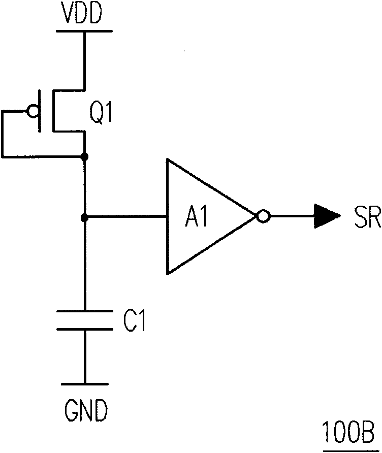
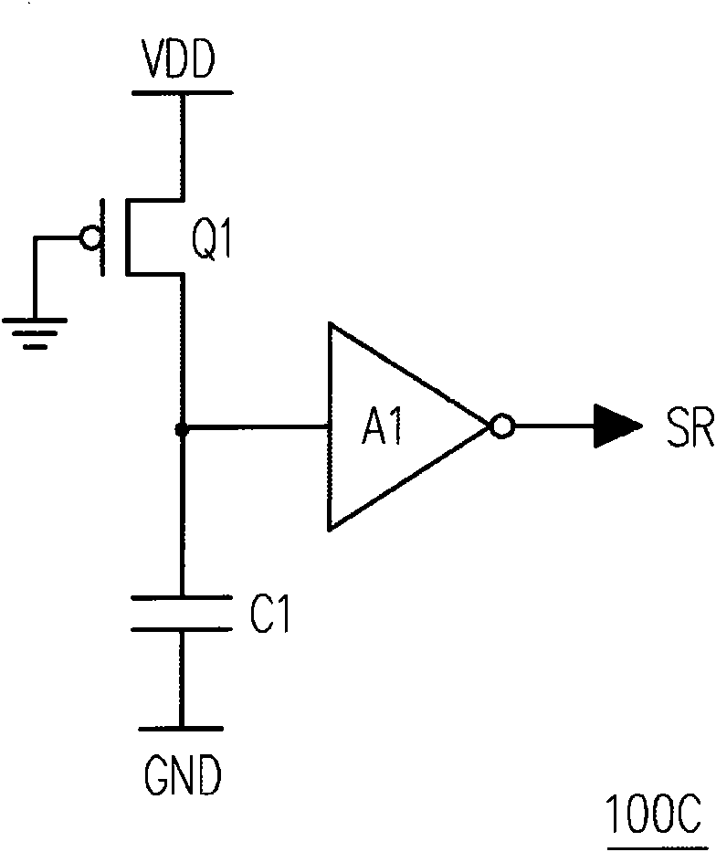
technical field [0001] The present invention relates to a reset circuit, in particular to a power on reset circuit for a power supply. Background technique [0002] When designing an electronic circuit, a reset mechanism is often added to the circuit, so that the designed electronic circuit can be restored to an initial state when needed. Especially when the electronic circuit is powered on (starting up), each element in the circuit (such as a temporary register) is in an uncertain state, and these circuit elements need to be reset at this time to set each element in the circuit to an initial state. [0003] Figure 1A Circuit diagram for the existing power reset circuit. Please refer to Figure 1A , The existing power reset circuit 100A includes a resistor R1, a capacitor C1 and an inverter A1. The resistor R1 is coupled between the power supply voltage VDD and the input terminal of the inverter A1, and the capacitor C1 is coupled between the input terminal of the inverte...

Claims


Application Information

Patent Timeline
IPC IPC(8): H03K17/22G01R19/00
Inventor 廖俊尧
Owner HOLTEK SEMICON
Learn More