
Retaining ring of mandrel of motor

A buckle and motor technology, applied in the direction of magnetic circuit shape/style/structure, magnetic circuit rotating parts, etc., can solve the problems of rotor 83 falling off, easy to crack, and overall strength reduction, so as to avoid noise and prevent rotor Shedding, avoiding the effect of smoothness

Active Publication Date: 2014-02-26
SUNONWEALTH ELECTRIC MACHINE IND
View PDF2 Cites 0 Cited by
  • Summary
  • Abstract
  • Description
  • Claims
  • Application Information

AI Technical Summary

Problems solved by technology

However, although each spacer 92 of the existing buckle 9 is inclined, the amount of deformation at the root of each spacer 92 can be reduced, but the thickness of each spacer 92 is still uniform, so the deformation cannot be solved. The amount is concentrated on the defect that each of the limiting members 92 has a uniform thickness, so that cracks or even breakage are easy to occur
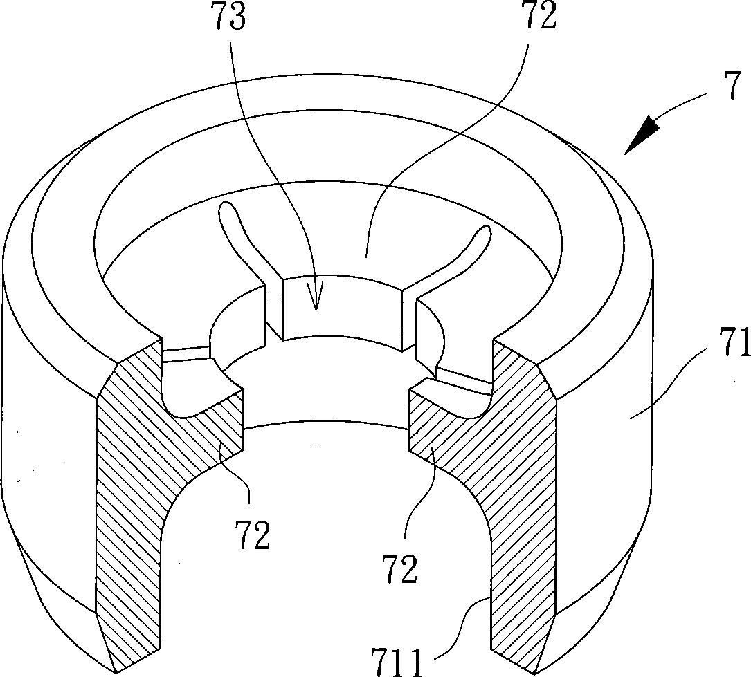
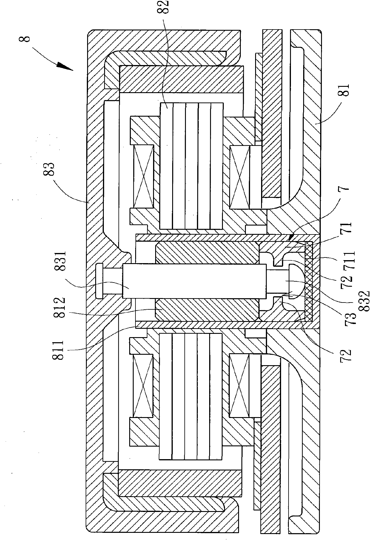
[0007] And when the stoppers 72, 92 of the aforementioned existing snap rings 7, 9 break, the broken stoppers 72, 92 fall inside the shaft tube 811, and follow the mandrel 831 continuously on the shaft tube 811. Noise due to internal whirling and collision
Moreover, when some limiters 72, 92 break, the overall strength of each limiter 72, 92 embedded in the buckle groove 832 of the mandrel 831 will also decrease, so when the motor 8 is subjected to an external impact, the It is easy to cause the rotor 83 to fall off

Method used


Image

  • Retaining ring of mandrel of motor
  • Retaining ring of mandrel of motor
  • Retaining ring of mandrel of motor

Examples


Embodiment Construction

[0036] In order to make the above-mentioned and other objects, features and advantages of the present invention more comprehensible, the preferred embodiments of the present invention are specifically cited below, together with the accompanying drawings, as follows:

[0037] Please refer to Image 6 and 7 As shown, the clasp 1 according to the first embodiment of the present invention includes a ring body 11 and a plurality of limiting parts 12 .

[0038] An inner hole 111 is formed at the center of the ring body 11 , and the inner hole 111 passes through a top surface 112 and a bottom surface 113 of the ring body 1 .

[0039] Each of the limiting parts 12 has a joint end 121 and a catch end 122, the joint end 121 of each of the limiting parts 12 is connected to the wall surface of the inner hole 111 of the ring body 11, and the locking of each of the limiting parts 12 The end 122 extends from the wall of the inner hole 111 toward the center and forms a shaft hole 13 around ...


PUM


Abstract

The invention provides a retaining ring of a mandrel of a motor. The retaining ring comprises a ring body and a plurality of spacing parts, wherein an inner hole is formed in the center of the ring body; each spacing part is provided with a combing end and a clamping end; the combining end of each spacing part is connected with the wall surface of the inner hole; the clamping ends of the spacing parts stretch from the inner hole wall to the center and surround so as to form a shaft hole; and each spacing part is provided with an upper surface and a lower surface, wherein the thickness of each spacing part is the axial direction distance between the upper surface and the lower surface; and the thickness of the combing end is the biggest, the thickness of the clamping end is the smallest, and the thickness of each spacing part is gradually reduced from the combining end to the clamping end. Therefore, when the retaining ring is applied to the motor, each spacing part is not easily crack or break in the assembling process.

Description

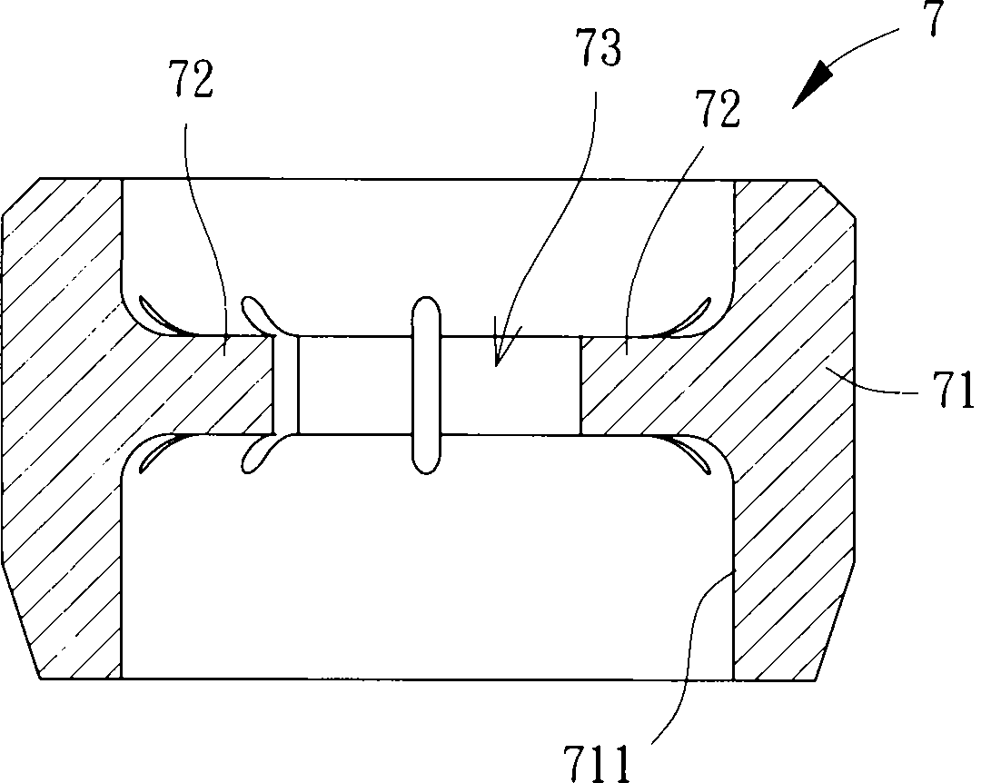
technical field [0001] The present invention relates to a clasp of a motor spindle, in particular to a clasp that can be engaged with the spindle of the motor so as to limit the motor rotor to rotate relative to the stator without breaking away. Background technique [0002] Please refer to figure 1 and 2 As shown, the existing clasp 7 includes a ring body 71 and several stoppers 72. An inner hole 711 is formed in the center of the ring body 71. Each stopper 72 is connected to the wall of the inner hole 711 and extends towards the center. , and each limiting member 72 is formed with a shaft hole 73 around it. [0003] Please refer to figure 1 and 3 As shown, when the existing clasp 7 is applied to a motor 8, the motor 8 includes a base 81, a stator 82 and a rotor 83, the base 81 has a shaft tube 811, and the clasp 7 is inserted into the shaft In the tube 811 , a bearing 812 is placed in the shaft tube 811 , and the stator 82 is fixed on the outer periphery of the shaft ...

Claims


Application Information

Patent Timeline
Patent Type & Authority Patents(China)
IPC IPC(8): H02K1/28
Inventor 洪银树
Owner SUNONWEALTH ELECTRIC MACHINE IND
Learn More