
Underground ultrasonic yield-increasing pumping device for coalseam gas

A coalbed methane well, ultrasonic technology, applied in the direction of mining fluid, earthwork drilling, wellbore/well components, etc., can solve the problems of high production and maintenance costs, large energy loss, and many moving parts, so as to reduce gas production costs and improve Efficiency of drainage and wide application range

Inactive Publication Date: 2012-03-14
龚大建
View PDF6 Cites 33 Cited by
  • Summary
  • Abstract
  • Description
  • Claims
  • Application Information

AI Technical Summary

Problems solved by technology

[0004] 1. There are many moving parts, the energy loss is large, the energy consumption is high, and the relative failure rate is high;
[0005] 2. The "negative pressure" formed in the underground production area is relatively weak, which is unfavorable for the production speed of coalbed methane;
[0006] 3. The cost of equipment is relatively high, and the total cost of a complete set of equipment is about 250,000 RMB;
[0007] 4. The cost of production and maintenance is high, and the pump is checked regularly, and the operation is more complicated;
[0008] 5 There is no effect on the stimulation of coalbed methane wells

Method used


Image

  • Underground ultrasonic yield-increasing pumping device for coalseam gas
  • Underground ultrasonic yield-increasing pumping device for coalseam gas
  • Underground ultrasonic yield-increasing pumping device for coalseam gas

Examples


Embodiment Construction

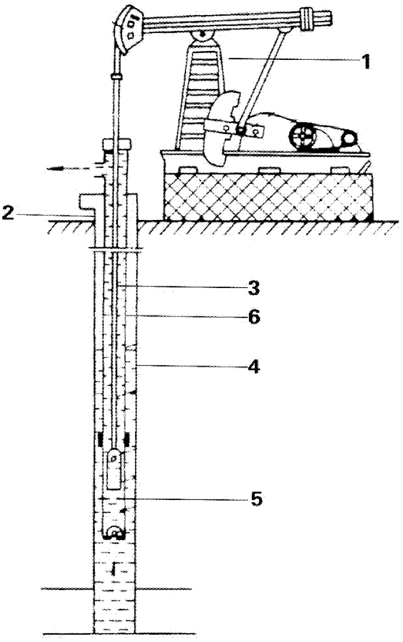
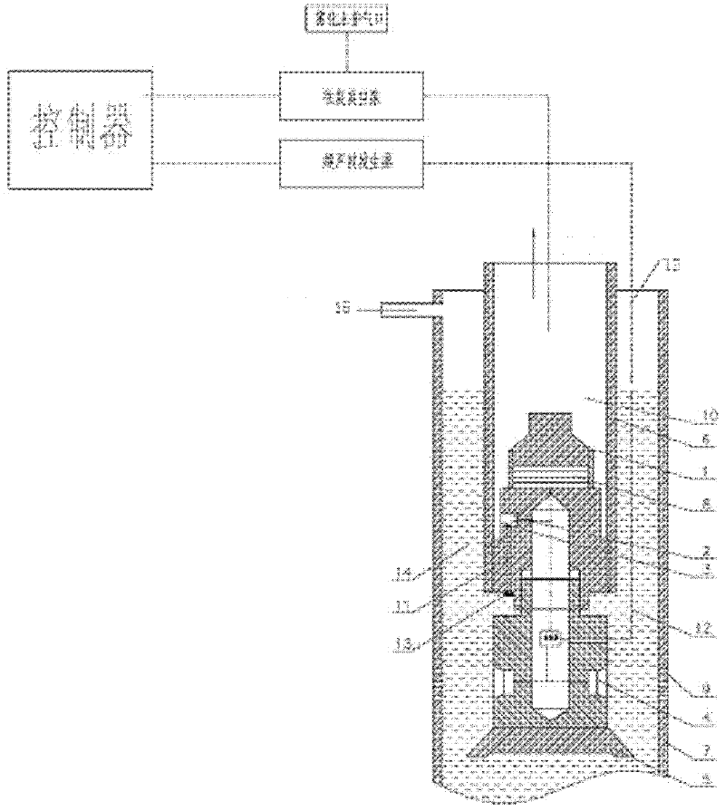
[0028] Below, in conjunction with accompanying drawing and embodiment, the present invention is described in detail; figure 1 It is a schematic diagram of the structure of a system device in the prior art that adopts the "liquid drainage and gas recovery" method and uses the ground pumping unit to drive the oil well pump. figure 2 It is a structural schematic diagram of a device supporting the ultrasonic stimulation and atomization extraction process of coalbed methane underground in the present invention. From figure 1 It can be seen that the surface pumping unit 1 drives the oil pump 5 through the sucker rod 2, and the piston of the oil pump 5 reciprocates up and down to continuously pump out the bottom water to reduce the height of the liquid column and make the pressure at the perforation position Above the liquid column pressure, a certain "production pressure difference" is formed; in this way, the desorbed gas of the coal seam flows out from the perforation position o...


PUM


Abstract

The invention discloses an underground ultrasonic yield-increasing and atomized pumping device for coalseam gas. A reciprocating vacuum pump and an underground ultrasonic wave generator are connected by a control cabinet. The underground ultrasonic wave generator is connected to the ultrasonic yield-increasing and atomized pumping device. The reciprocating vacuum pump is connected to oil pipes. A casing pipe provided with an oil pipe is deeply inserted into a coalseam. An oil pipe opening is higher than a casting pipe opening. The ultrasonic yield-increasing and atomized pumping device is installed at the lower end in the oil pipe and used for sealing the oil pipe lower opening. The device includes: a high-power ultrasonic atomization transducer and a yield-increasing device ultrasonic transducer. The lower end of the high-power ultrasonic atomization transducer is connected to the yield-increasing device ultrasonic transducer, and is extended the lower end of the oil pipe opening. An inlet duct communicated with the casting pipe inner chamber is arranged in the oil pipe. A filter screen, a solenoid valve and a liquid level sensor are arranged in the inlet duct. The lower wall of the casting pipe is provided with eyeholes. A coalseam opening is arranged out of the casting pipe above the ground. According to the underground ultrasonic yield-increasing and atomized pumping device disclosed by the invention, the pumping operation for the coalseam gas can be completed, no mechanical motion occurs, and the advantages of saving energy, increasing the total desorption amount of the coalseam gas, reducing the cost and being simple in maintenance are achieved.

Description

technical field [0001] The invention relates to an ultrasonic production increase extraction device for underground coal bed methane, which belongs to the field of coal bed methane extraction. Background technique [0002] Coal bed methane is a kind of desorbed gas adsorbed on coal seams. During the development process, water always flows out from the coal seams. During production, a liquid column with a height of about 50-80 meters is formed in the wellbore, and the pressure of this liquid column greatly affects Gas production capacity of coalbed methane. In the existing production technology, the oil and gas development method is basically copied, and the basic idea is "gas extraction by liquid drainage" (see attached figure 1 ), the surface pumping unit 1 drives the oil pump 5 through the sucker rod 2, and the piston of the oil pump 5 reciprocates up and down to continuously pump out the bottom well water to reduce the height of the liquid column, so that the formation ...

Claims


Application Information

Patent Timeline
Patent Type & Authority Applications(China)
IPC IPC(8): E21B43/00E21B43/26
Inventor 龚大建
Owner 龚大建
Learn More