
Electromagnetic load reduction bearing for hydraulic generator

A technology for hydroelectric generators and bearings, which is applied to bearings, shafts, bearings, mechanical equipment, etc. It can solve the problems of coil insulation performance degradation, high processing and maintenance costs, and high bearing precision requirements, and achieve the effect of no lubrication life

Inactive Publication Date: 2012-02-29
SOUTHWEST JIAOTONG UNIV
View PDF2 Cites 8 Cited by
  • Summary
  • Abstract
  • Description
  • Claims
  • Application Information

AI Technical Summary

Problems solved by technology

However, in actual operation, sliding bearings are generally lubricated with lubricating oil, and dynamic pressure lubrication will generate a large amount of oil mist
However, the bearing oil tank adopts dynamic seal, and there is inevitably a sealing gap. Due to the limitation of the performance of the sealing material, the oil mist will overflow from the oil tank, which not only pollutes the air, but also adheres to the coil of the motor, resulting in a decrease in the insulation performance of the coil, forming a major hidden danger
At the same time, for large-sized and high-speed units, due to the large bearing load, high bearing precision requirements, high processing and maintenance costs, and huge bearing loss during operation, the bearing cooling system matching the bearing loss is complex

Method used


Image

  • Electromagnetic load reduction bearing for hydraulic generator
  • Electromagnetic load reduction bearing for hydraulic generator
  • Electromagnetic load reduction bearing for hydraulic generator

Examples


Embodiment Construction

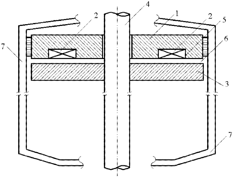
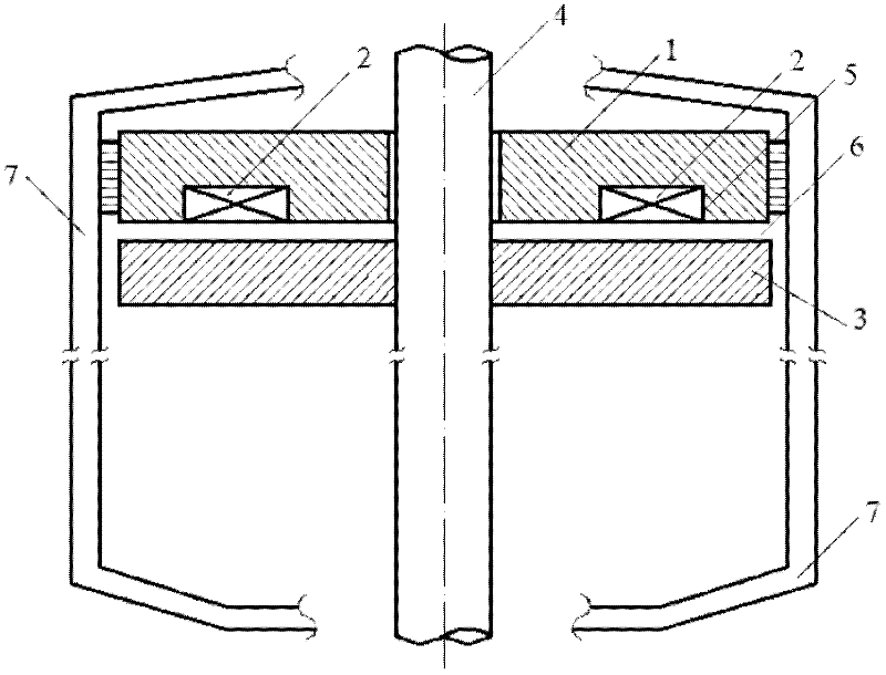
[0009] Such as figure 1 As shown, the electromagnet is fixed on the motor stator 7 and consists of a ferromagnetic material iron core 1 and a coil 2, and the coil 2 is embedded in a groove 5 of the ferromagnetic material iron core to form an electromagnet. Thrust disc 3 is made of ferromagnetic material and is fixed on motor rotor 4 . The gap 6 between the electromagnet and the thrust disc can be set according to specific requirements. According to different motor rotor load reduction requirements, the suction force between the electromagnet and the thrust disc can be adjusted by adjusting the current in the electromagnet coil 2 through the control system.

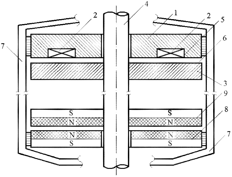
[0010] The load-reducing bearing can be installed and used in multiple positions in the hydro-generator, and the electromagnetic bearing can also be made into various structures. For example, the load-reducing bearing can be additionally provided with permanent magnets arranged opposite to each other with the same pole be...


PUM


Abstract

The invention discloses an electromagnetic load reduction bearing for a hydraulic generator, which is arranged on a motor stator. The load reduction bearing is of the following structure that an iron core 1 made of a ferromagnetic material is fixed on the motor stator 7; a coil 2 is embedded into a groove 5 of the iron core made of the ferromagnetic material to form an electromagnet; a thrust disc 3 made of the ferromagnetic material is fixed on a motor rotor 4 and is arranged in a mode of facing the side of the groove of the electromagnet; a gap 6 is reserved between the electromagnet and the thrust disc; and a lead wire in the coil 2 is connected with the control system. Compared with a conventional sliding bearing, the electromagnetic bearing has the characteristics of environment protection and low consumption and has wide application range. The environment pollution can be reduced. The energy consumption can be reduced. The electromagnetic load reduction bearing has outstanding advantages.

Description

Technical field: [0001] The invention relates to machine parts, especially the field of hydroelectric generator equipment manufacturing. Background technique: [0002] Hydrogenerator thrust bearings usually bear a large thrust load, and the linear velocity of relative sliding between friction pairs should reach several meters per second to tens of meters per second. Generally, hydrodynamic sliding bearings are used (a few hydrostatic sliding bearings are used). However, in actual operation, sliding bearings are generally lubricated with lubricating oil, and dynamic pressure lubrication will generate a large amount of oil mist. However, the bearing oil tank adopts dynamic seal, and there is inevitably a sealing gap. Due to the limitation of the performance of the sealing material, the oil mist will overflow from the oil tank, which not only pollutes the air, but also adheres to the coil of the motor, resulting in a decrease in the insulation performance of the coil, forming ...

Claims


Application Information

Patent Timeline
Patent Type & Authority Applications(China)
IPC IPC(8): F16C32/04
Inventor 蒋启龙姚卫丰岳德坤
Owner SOUTHWEST JIAOTONG UNIV
Learn More